
Parametric and FEA
This assignment provided students with the opportunity to learn and practice parametric design and FEA. Parametric design is defined by a design process that relates to specific parameters, often parameters that relate to each other. This type of design allows for dynamic changes and alterations to the design depending on the values of variable parameters. For the other portion of this assignment, FEA stands for finite element analysis. FEA is a process that allows calculations of how a design reacts to certain forces for the purpose of understanding the stress or strain on the design. (There are wider applications and results from FEA, but this assignment focuses on the stress created by an applied force.) FEA is also included in most CAD software for ease of use with modeled designs.
Objectives
- Use axial deflection modeling to design its dimensions
- Use parametric design to determine a bars length
- Introduce you to FEA (Finite Element Analysis)
- Introduce you to linking dimensions to appropriate parameters in CAD.
- Compare and contrast the different analysis
Description
"You are to design a bar which has a hollow triangular cross section where the values of the criteria given for the material, maximum deflection, and load. Determine the bar’s minimum geometry (ie.. length, height, weight, and thickness) through parametric design while under direct tension. Then verify the geometry through finite element analysis."
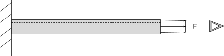
Figure #1. Sketch of cantilever hollow box beam with distributed load.
My Process
Pre-CAD
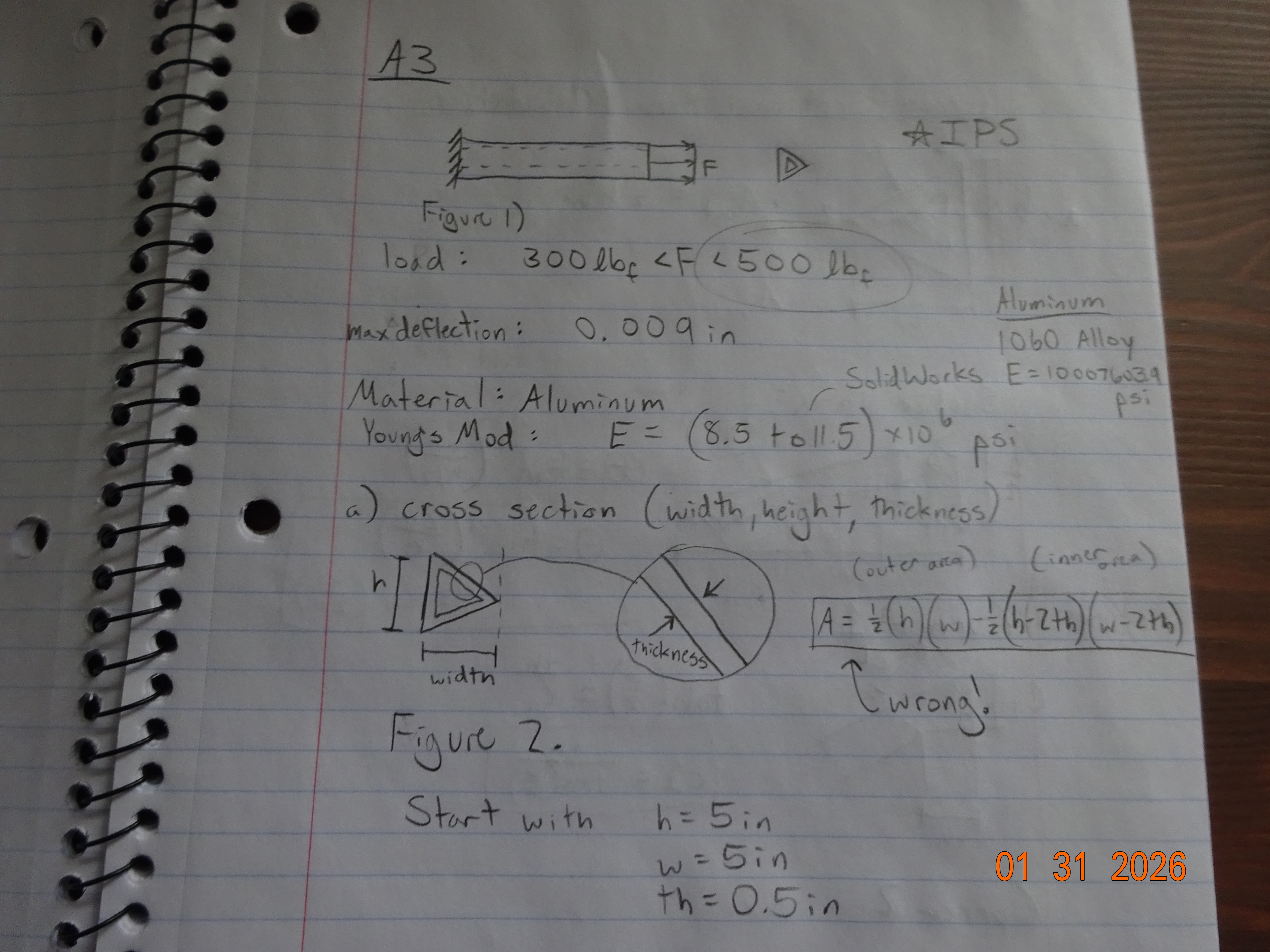
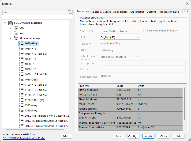
To begin my design process, I always like to rewrite the given information onto my workspace. I made sure to include Figure #1, the range for the load, max deflection, material, and range for Young's modulus. I made a note to myself in the top of the page that I would be working in IPS units later in CAD, and so I would do all my calculations as given in the assignment specifications of inches, pounds, and psi. I also utilized SolidWorks to determine the Young's modulus that I would be designing with. I selected an Aluminum Alloy of 1060 Alloy. This material was listed with Young's modulus (E) equal to 10,007,603.9 psi which fit the range in the specifications of the assignment. I then re-sketched the rough cross-section view of the triangular hollow beam. This can be seen in my work as Figure #2, and I label height (h), width (w), and thickness (th) as my variable parameters. For my initial test and modeling, I selected some semi-arbitrary values of h=5in, w=5in, and th=0.5in. I also wrote an equation to find the area of this cross section, although I later came back to find that there was an error in my thinking and it was an incorrect equation for the area I drew.
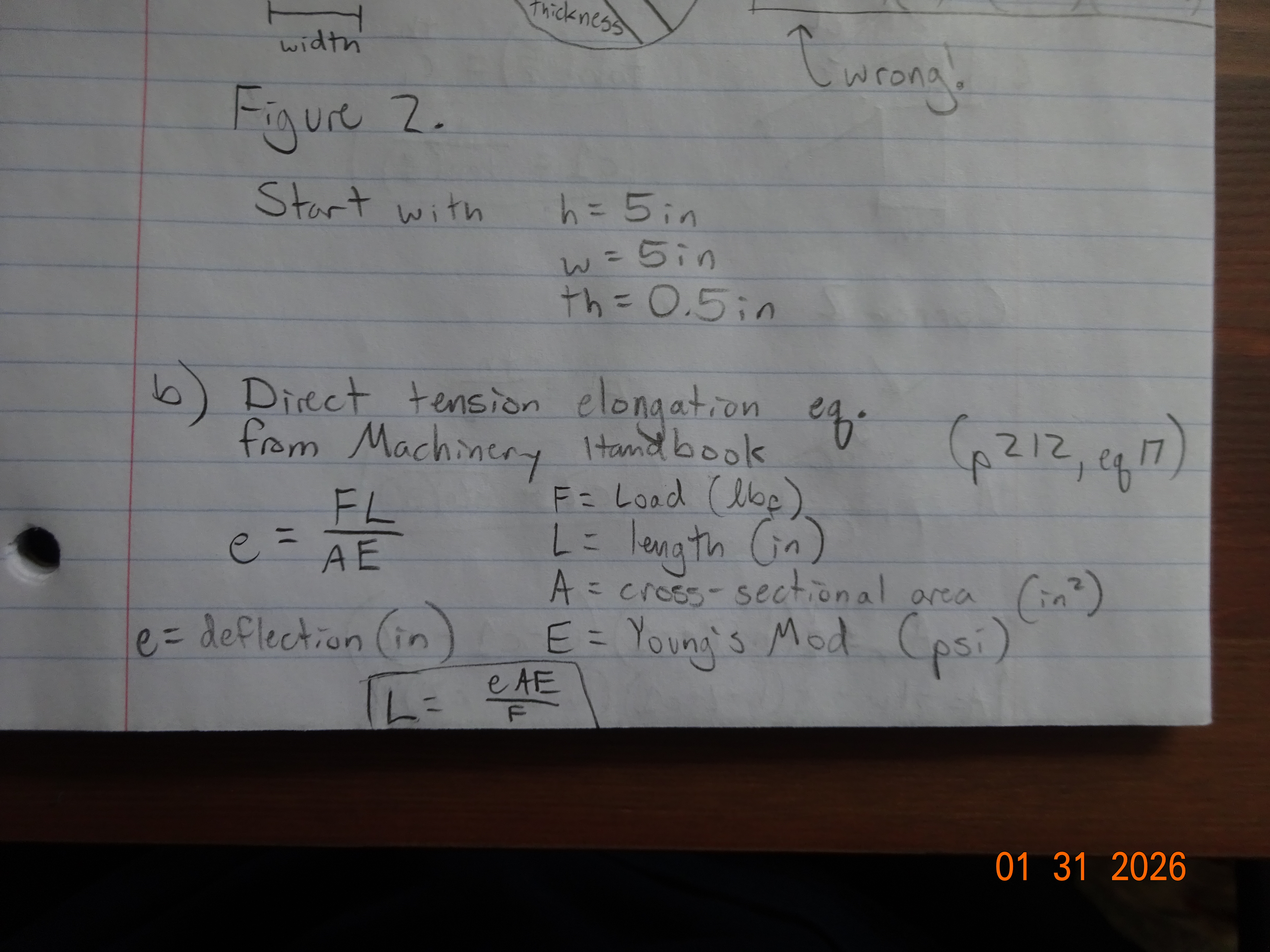
Next, to determine the length of the beam, I would need to utilize an equation for direct tension elongation. The assignment directed me to utilize the equation found in the Machinery Handbook (I have the 32nd Edition). The equation is located on page 212 as equation (17) which states . I made sure to note what units my variables should be in as well as what each letter represents, and then continued by moving into my CAD software of choice, SolidWorks.
CAD Modeling the Cross-Section
My first action in SolidWorks were to make sure that I was working in IPS units and select my sketch plane. Since I wanted to be able to view the length of the beam from the front view, I started my cross-section sketch on the right plane. I aligned the bottom left corner to the origin, and then made sure that the two sides on the right side of the triangle would be equal, by giving them an equal relation. I then added my variables into the equation tool so that I could add them to the dimensions of the sketch. Once I had the outside dimensions, I created an offset which I set to be the thickness.
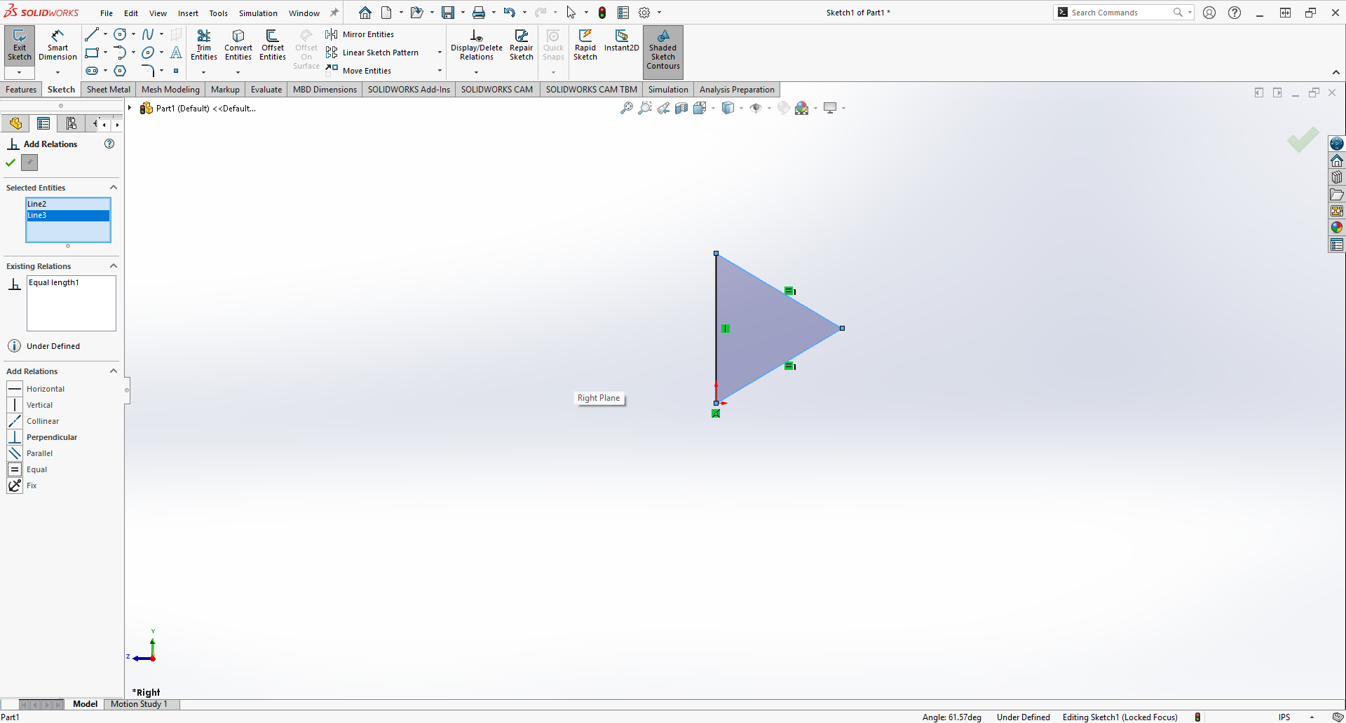
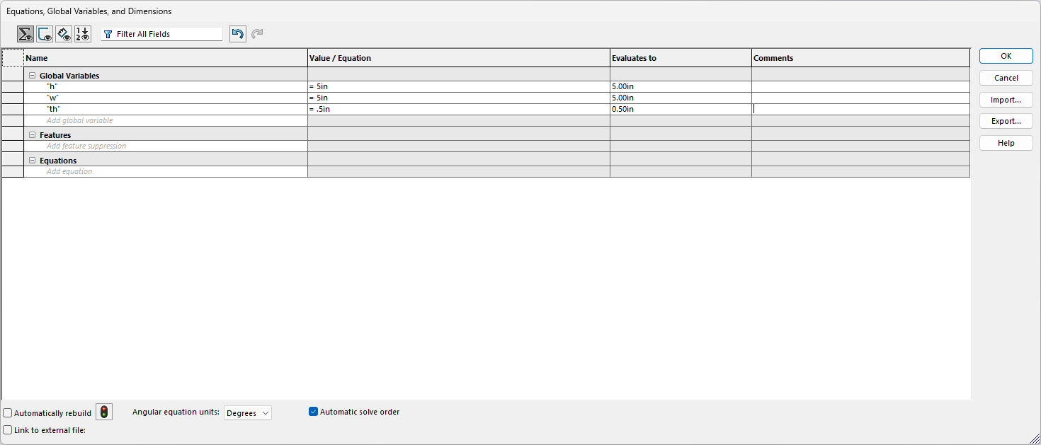
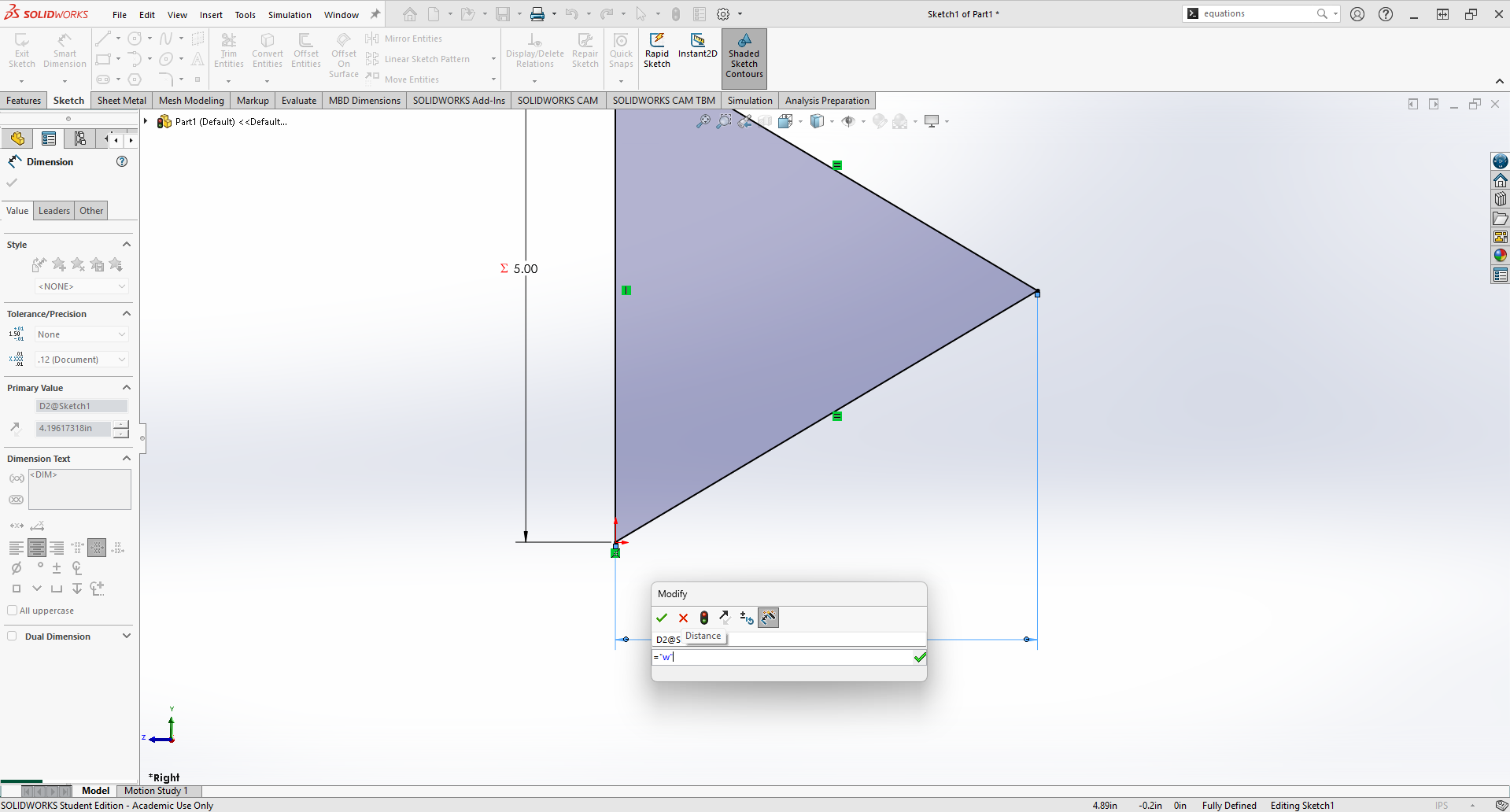
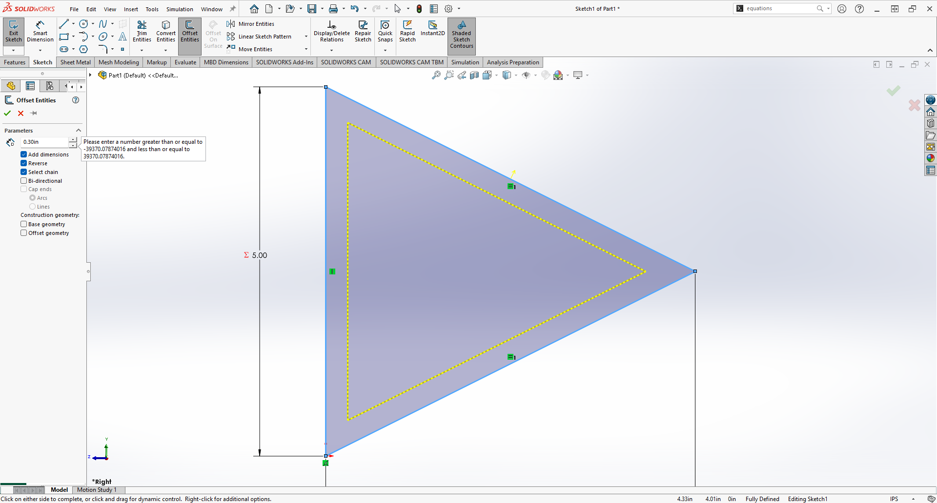
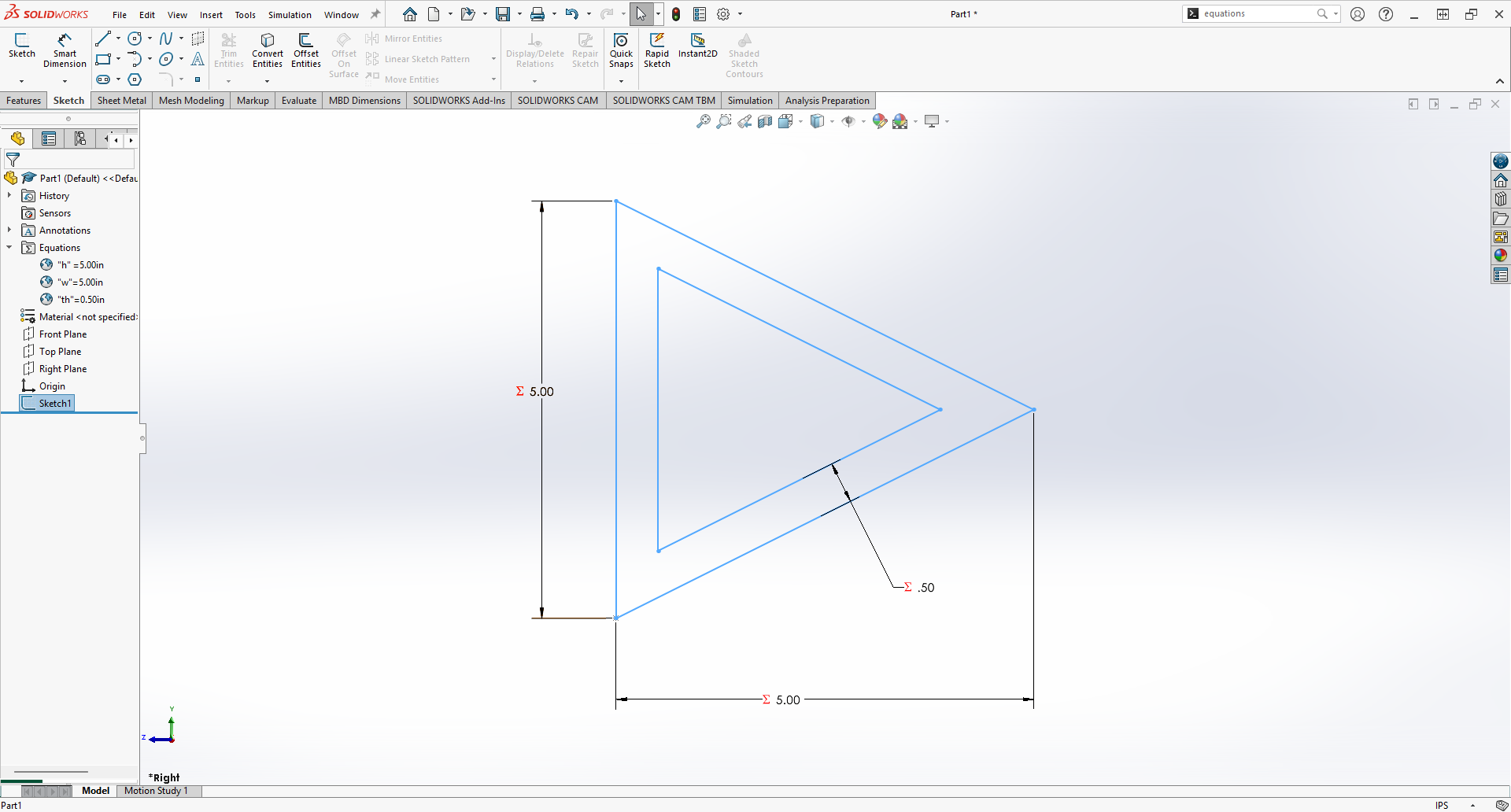
Figure #3. Cross Section of Beam Model with Parametric Dimensions
Once I saw the sketch in Figure #3, I quickly realized that I had made a flaw in my earlier cross-sectional area equation. I had assumed that the values of "h" and "w" would both be reduced by two times the thickness. Because of the angles of my triangle and the nature of the offset this was incorrect and only became apparent once I saw the sketch. To confirm my suspicions, I utilized SolidWorks' measure tool to see the distance between one of the inner and outer corners, and I was assured that my original thought process was wrong since the value was not equal to the thickness.
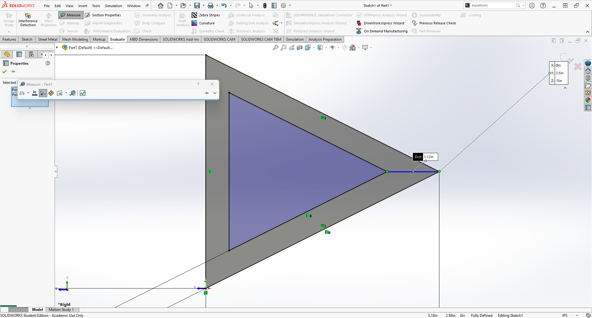
This gave me two options, one was to redefine the sketch in a way that the interior triangle did match the values I had made in my initial area equation. The second option was to go through the geometry and trigonometry to find the actual values I needed to calculate the interior area. I decided that option two felt more correct for this assignment and proceeded to redefine my area equation. I will include an image of my work to come to the values I needed as well as a final more accurate area equation.
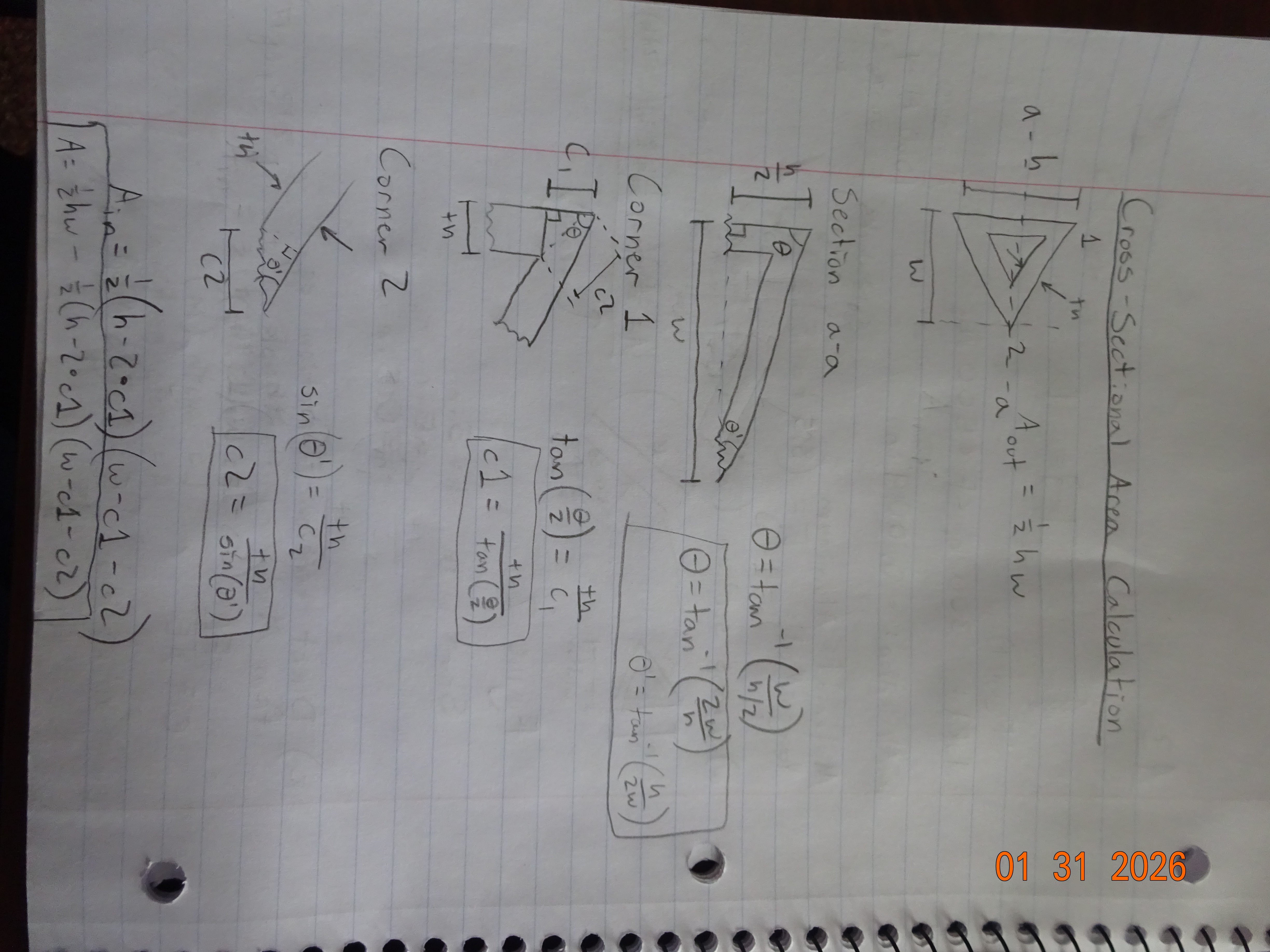
Later I came back to compare the accuracy of my equation to how SolidWorks evaluated the cross-sectional area, and they ended up being very close. The values were only twenty thousandths of a square inch off, which I felt was close enough for the purposes of this assignment.
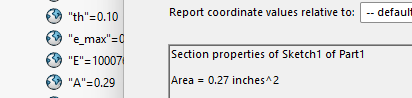
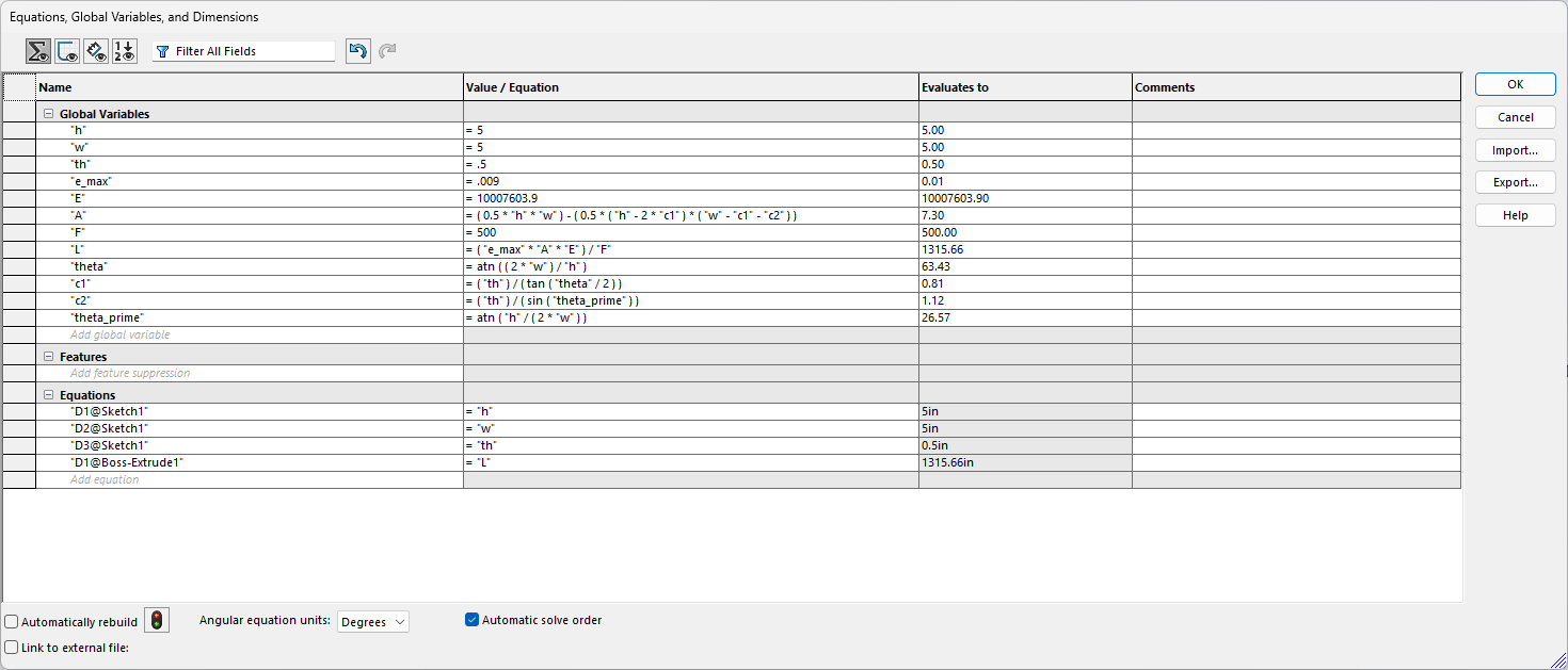
Now that I had all of my values and necessary equations, I input everything I needed into the Equation Tab in SolidWorks. The order is not perfect, but all necessary values are included to be able to calculate the cross-sectional area and subsequent length for the given load. It is important to note that I decided on the larger bound of the load range for this assignment which is 500 pounds of force.
CAD Model Beam Length
Now that I had my cross-section complete, I was able to create the extrusion that would become the beam length. I defined the extrude to be the parametric variable "L" calculated through my other dimensions, and was presented with the following beam and length. (1315.66 inches)
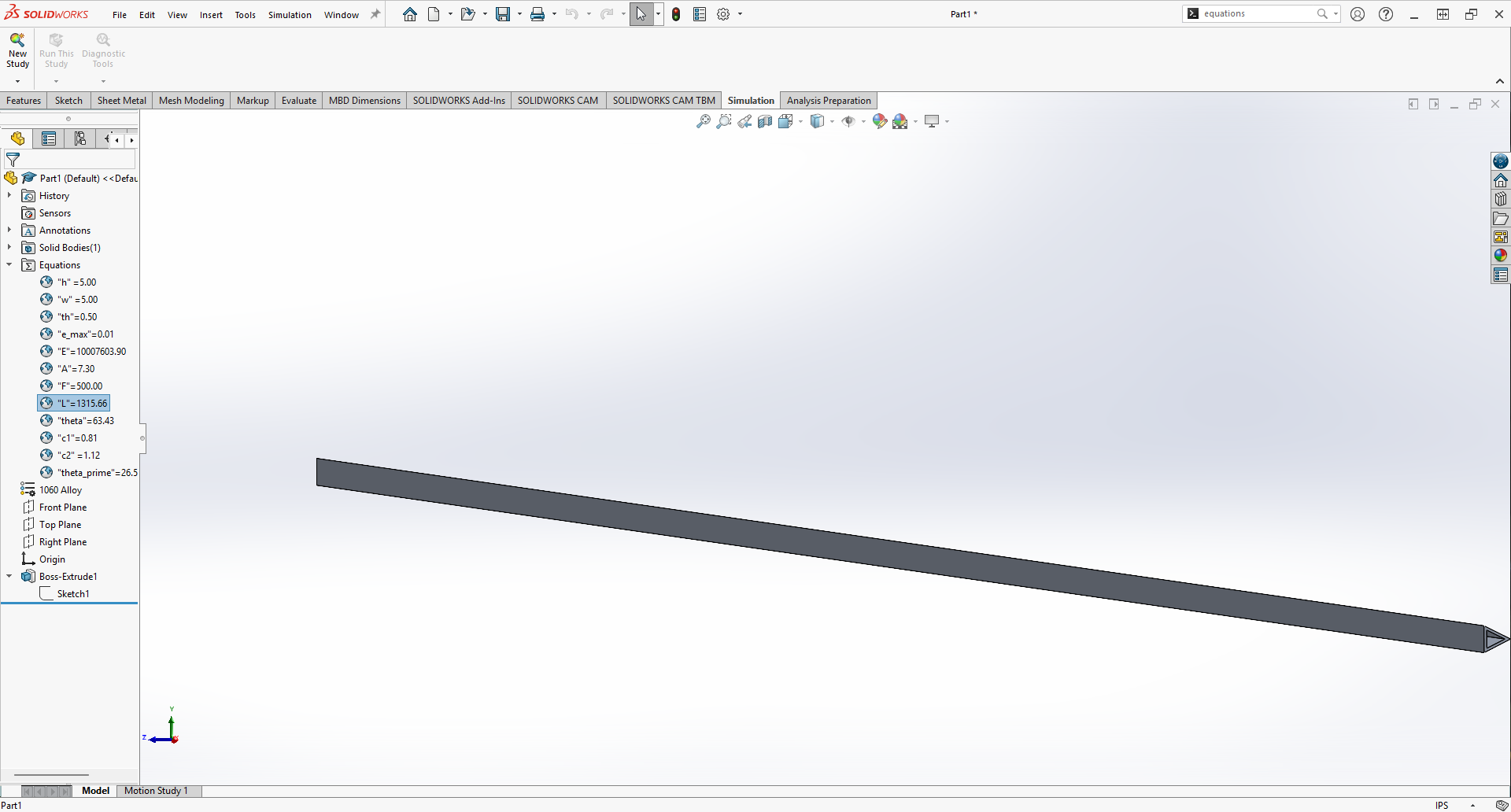
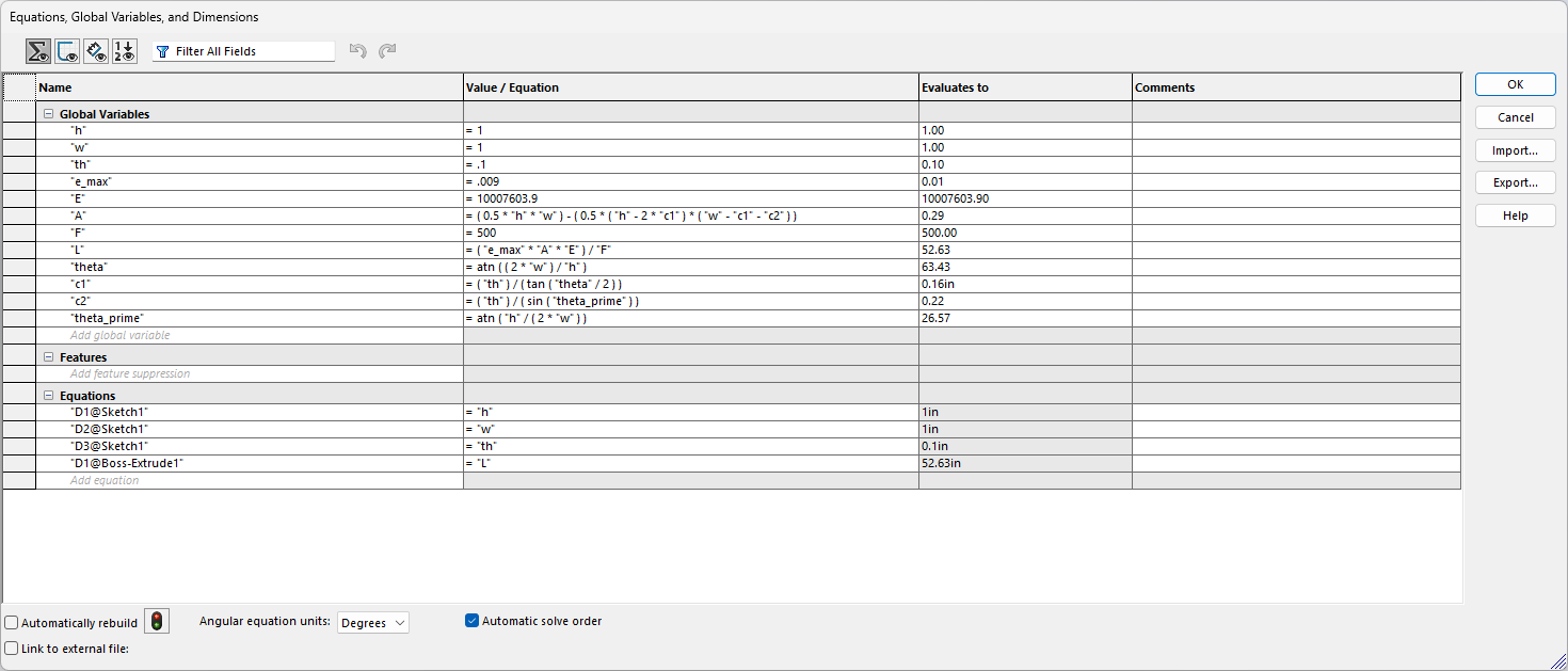
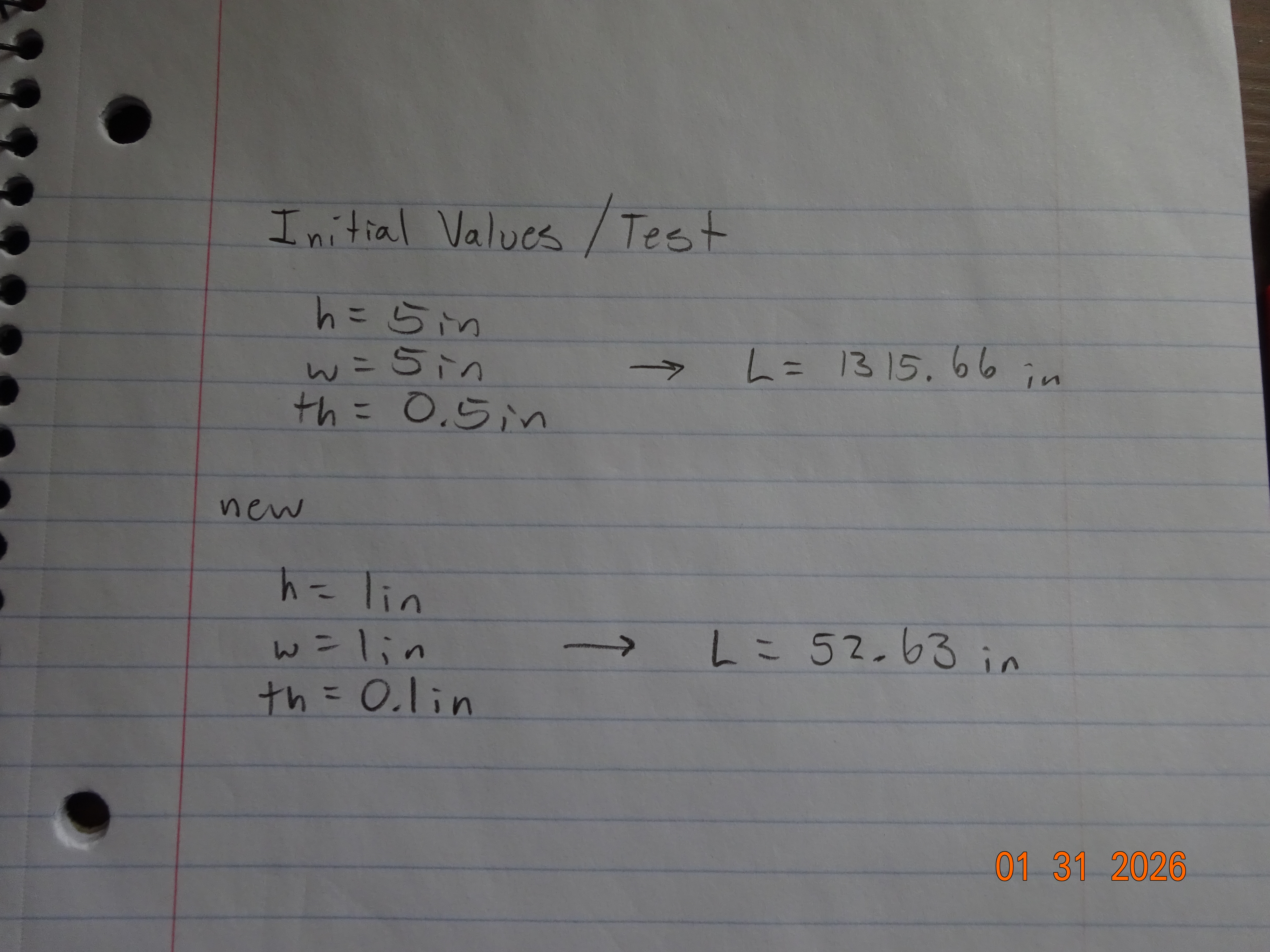
I proceeded to use this beam for a practice test of performing FEA, but quickly realized that my beam was far too long since I could barely fit the whole model on screen as I was viewing the stress and deflection analyses. This reminded me of the example that we were shown in the class lecture, when the professor showed us dynamically how changing the dimensions of the area related to the length. To shorten my beam without changing any of the specifications for Young's Modulus, applied load, or max deflection, I simply needed to make my cross-sectional area smaller. I went into my the Equation Tab, and edited my values for "h," "w," and "th." By reducing these values to 1in, 1in, and 0.1in respectively, I recieved a new beam length of only 52.63 inches.
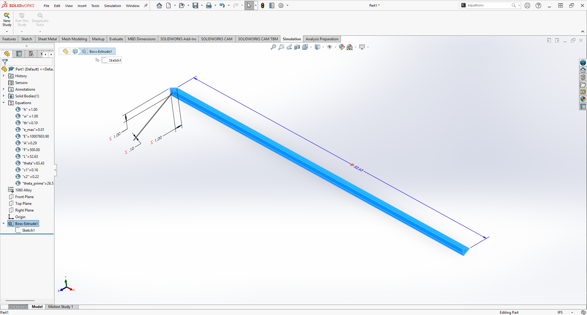
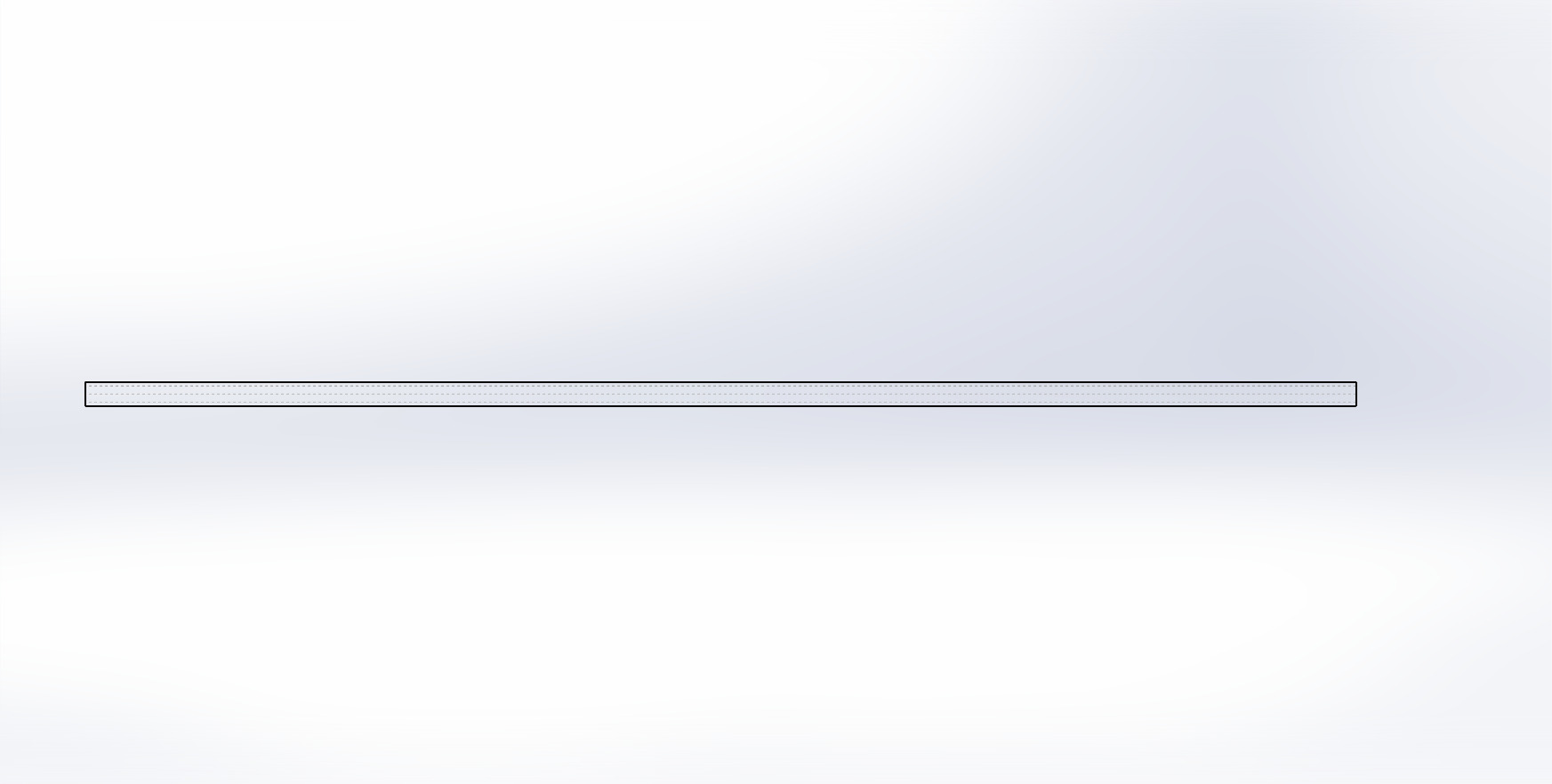
The images below are screencaptures from SolidWorks showing the view of my final beam design in the orientation style of Figure #1.

Finite Element Analysis (FEA) Setup
To begin the FEA, I started a new study under the Simulation Tab in SolidWorks. I selected a static study and began by defining one end of the beam as my fixture side and added the 500 lb tension force to the other side of the beam.
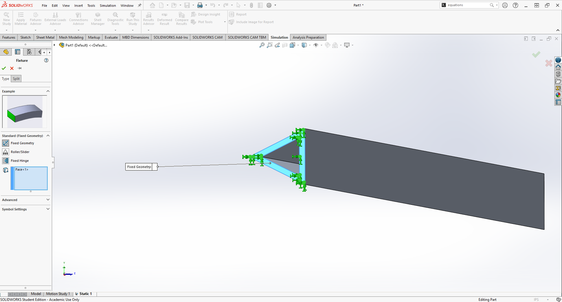
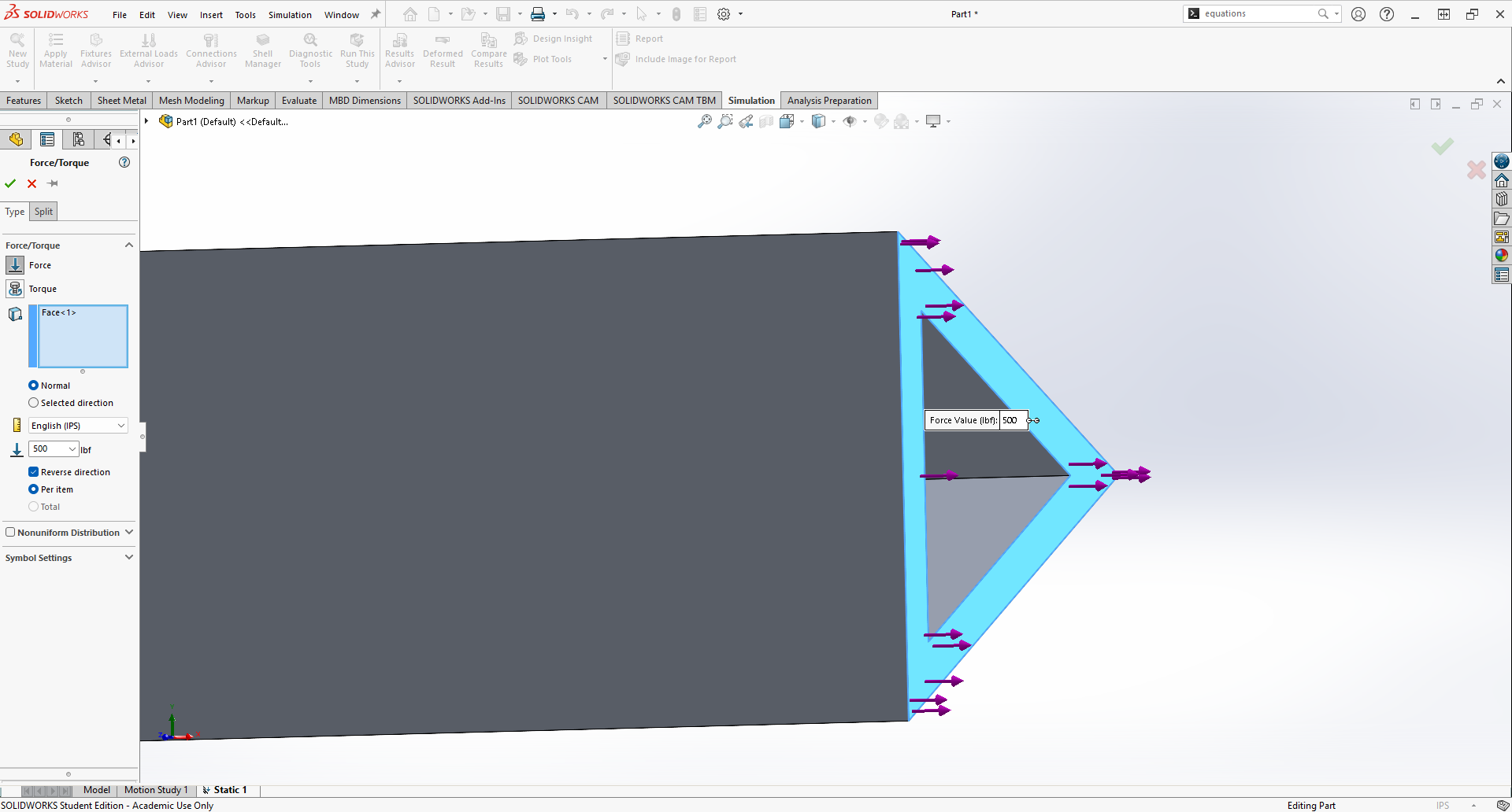
Once I had the fixture and load defined, I continued to run the simulation.
FEA Results
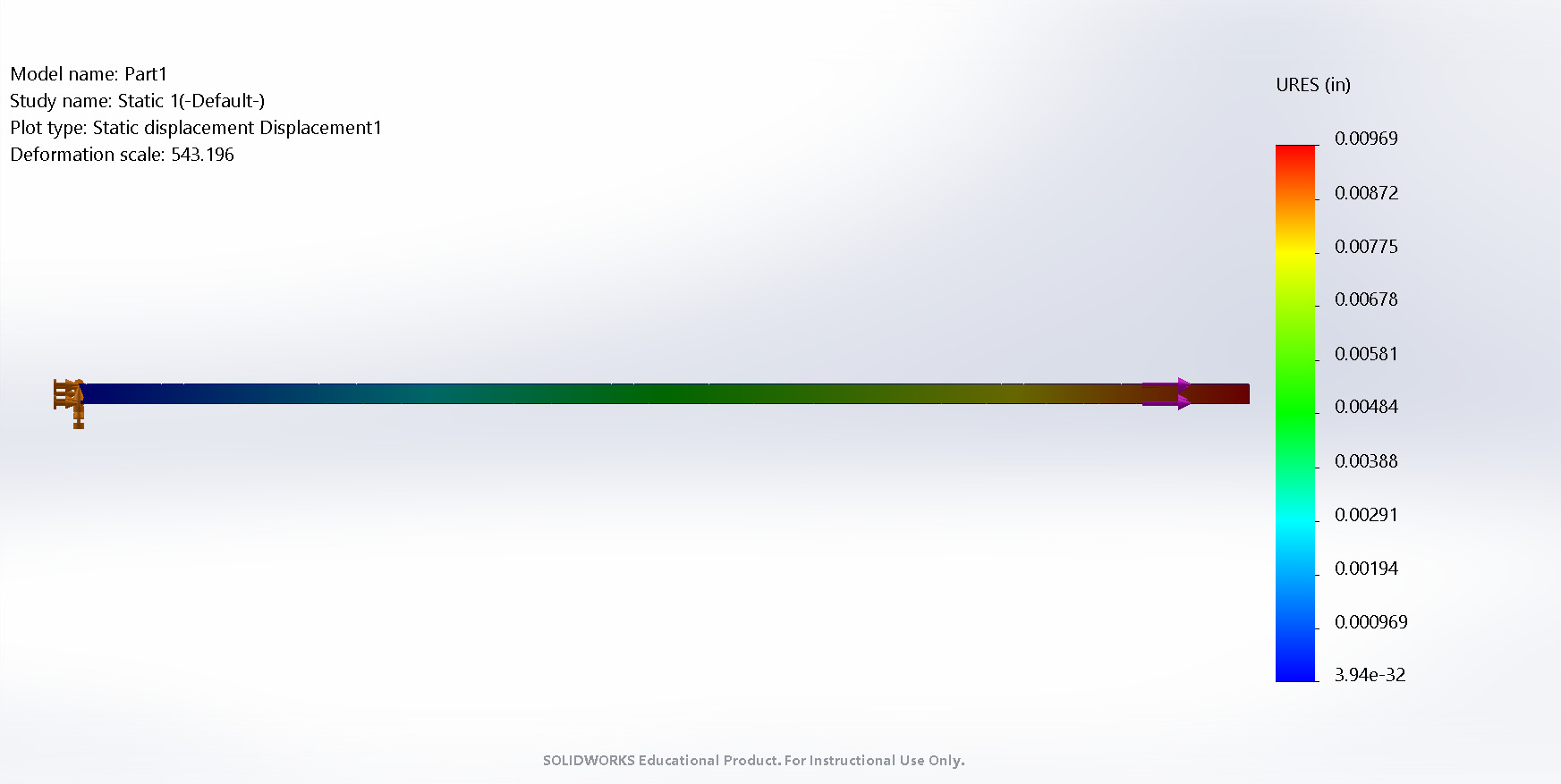
The first result that we were to observe was the deflection map. The image below shows a screencapture of this map along with the legend showing that the max deflection of this study was 0.00969 inches. The max deflection that was specified was 0.009 inches. I realize that when rounded my value does technically exceed this deflection, but since I utilized the larger bound of the force, I know that I would be below the max deflection for the lower loads. I am a little disappointed that the max load would be about one thousandth of an inch over the given max deflection, but I feel that this value is still satisfactory for the assignment. I presume that this small error could be accounted for in the cross-sectional area difference of my equation versus SolidWorks Evaluation. This difference may be due to the intermediate values like "theta," "theta_prime," "c1," and "c2" that I utilized to solve the area. I did not specify how many significant digits were needed for those intermediate values, and it likely resulted in an amount of rounding error compared to SolidWorks' Evaluation and Simulation tools.
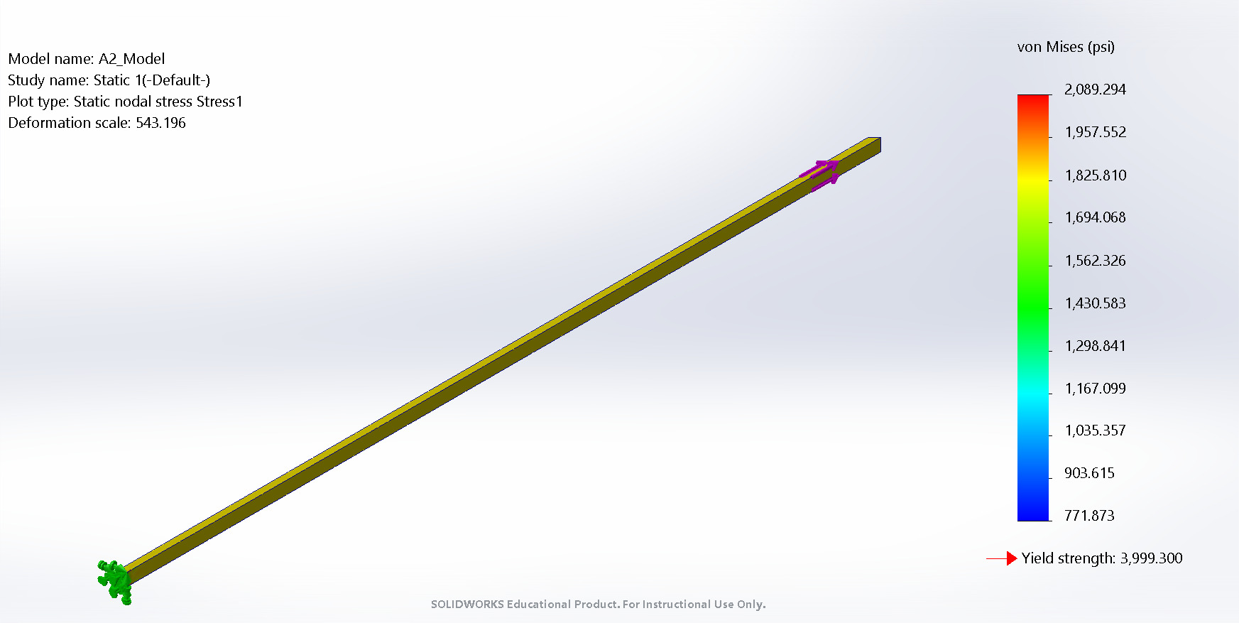
The second result that we were to observe was the von Mises stress map. The image below shows a screencapture of this map along with a legend and yield strength of the beam. This yield strength is important for making sure that the material can perform at this level of stress. Students were told to compare the yield strength of the simulation to a given yield strength of Aluminum which was said to be 40 ksi. Although this is the value we were given, my beam material in SolidWorks is an aluminum alloy with a yield strength of only 4 ksi. My study performed with a maximum stress of roughly 2,090 psi or 2.09 ksi which puts the beam below the material's yield strength of 4 ksi. The safety factor of this beam can then be calculated by taking material's yield strength and dividing it by the simulation yield strength. This gets a safety factor of 1.91. This is not a large safety factor, but it feels like a satisfactory result for this beam design.
Compare and Contrast the Beam's Deflection from Both Cases
When analyzing the two different FEA tests, it becomes clear that the parametric design was catered to only one test. This would be the deflection, since the parametric design's purpose was to use the minimum calculated length necessary to meet the maximum deflection specification. This axial deflection is due to the strain that the force creates on the beam. The Young's Modulus as defined by the material is the only connection of strain to stress in the parametric equations. This is why the maximum stress in the beam is not equal to the materials yield strength. The beam could be designed/optimized to meet the maximum yield strength, but this was not the purpose of the assignment and creates the danger of exceeding the yield strength of the material. Instead, the beam design was defined by the maximum deflection which allowed us to find a safety factor from the strength instead. The FEA showed that the parametric calculation for length was extremely accurate in relation to the maximum deflection down to about 1 thousandth of an inch. It also proved that the beam would stay below the material yield strength, which means that this design is satisfactory for the specifications given.
Model Download
I will include a download link for my design. This is not a .zip file that includes the FEA static study data performed for the assignment, but it is set up that the simulation can be run once downloaded.
You can download the .prt/.sldprt here.