
Bracket Drawing
Assignment Description
As part of this assignment, you will need to generate a comprehensive solid model and a multi-view engineering drawing that accurately represents your designed bracket, incorporating all features to ensure both strength and stiffness requirements are met.
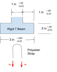
Figure 1.) Specification Visual of the rigid body the bracket affixes to and the polyester strap the bracket needs to hold
"Note: From the previous assignment “The bracket is designed to smoothly slide over the rigid T beam intended for applications where strict accuracy is not crucial.” Additionally, the change in the specifications have changed the T feature."
"Take note of the flange width dimension change from A5 (0.498in now instead of 0.5in from A5)."
*Description comes directly from the Assignment made by Dr. Fagan
My Process
Pre-CAD
This assignment builds heavily upon the design calculations made in assignment five. That being said, I noticed some small errors and flaws in the design I had previously. The first error I noticed was that I forgot to include the safety factor in many of the stiffness analysis calculations. Rather than continuing to this assignment with compromised dimensional values, I chose to quickly redo all the calculations from the previous assignment while taking extreme care to use correct formulas, include all factors, and make slight tweaks to the models when I felt it was necessary.
I also chose to calculate my new dimensions with zero buffer between the T-beam and the bracket. I thought that this change would be beneficial since we had just covered fits in our lecture and I hoped to be able to use the standard fits to create clean standardized tolerances for my bracket where it interacts with the T-beam. Unfortunately, this would later come back to bite me, since I left hardly any margin for my tolerances if I wanted to use my calculated geometry. This will be discussed in more detail later during the Drawing and Tolerance section.
The math and calculation process is very similar to the previous assignment, so I am not including all the photos here. If you would like to view the calculations, the full work can be found through the attached pdf at the bottom of this page.
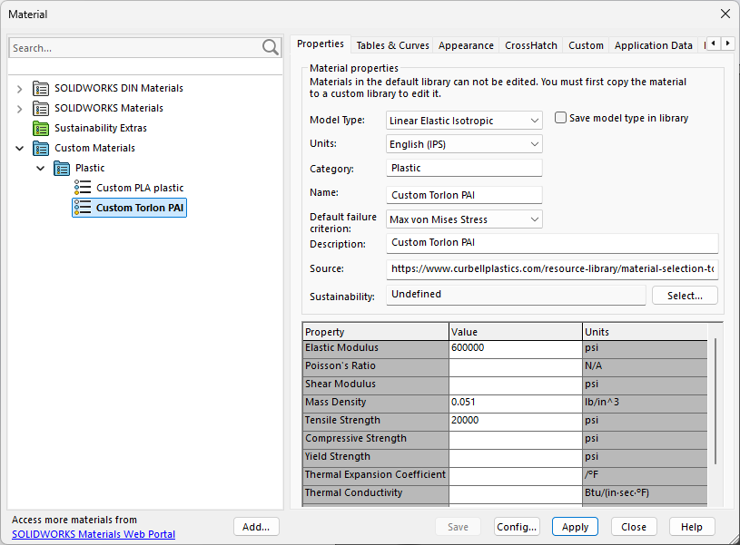
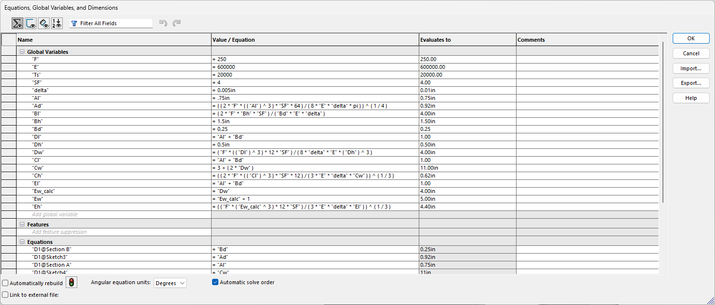
With the corrected dimensions, I was able to again determine which analysis yielded larger dimensions. It was still the stiffness analysis, so I knew to create my 3D model using the stiffness calculations to ensure that the design would be suitable for both my stress and stiffness constraints. Next, I was able to move into my CAD software and begin setting it up for the model. I started by adding my custom material and adding all my variables and calculated parameters into the equation section.
CAD Model
Now that I had my parameters set up, I was able to quickly create the 3D model using sketches and extrusions. The following images show the section geometry in the order that I designed them. I also labeled each section's extrusion for easier identification and model editing.
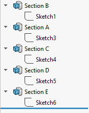
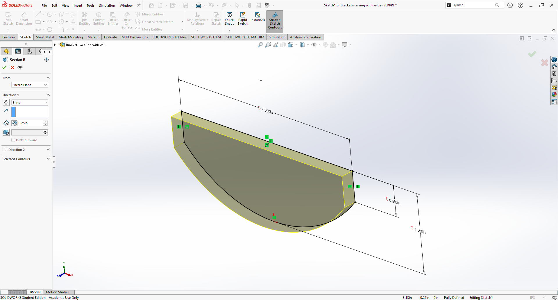
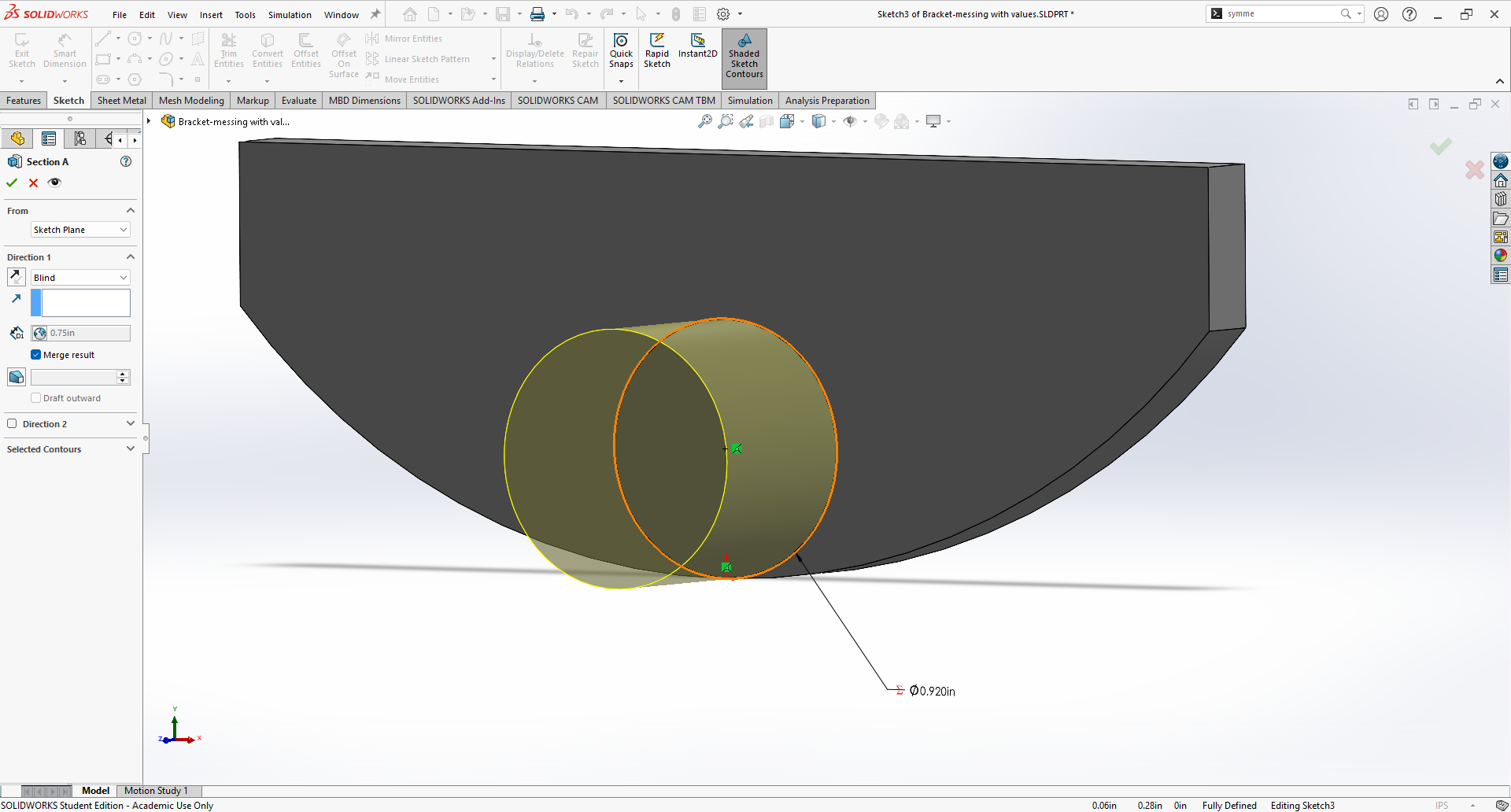
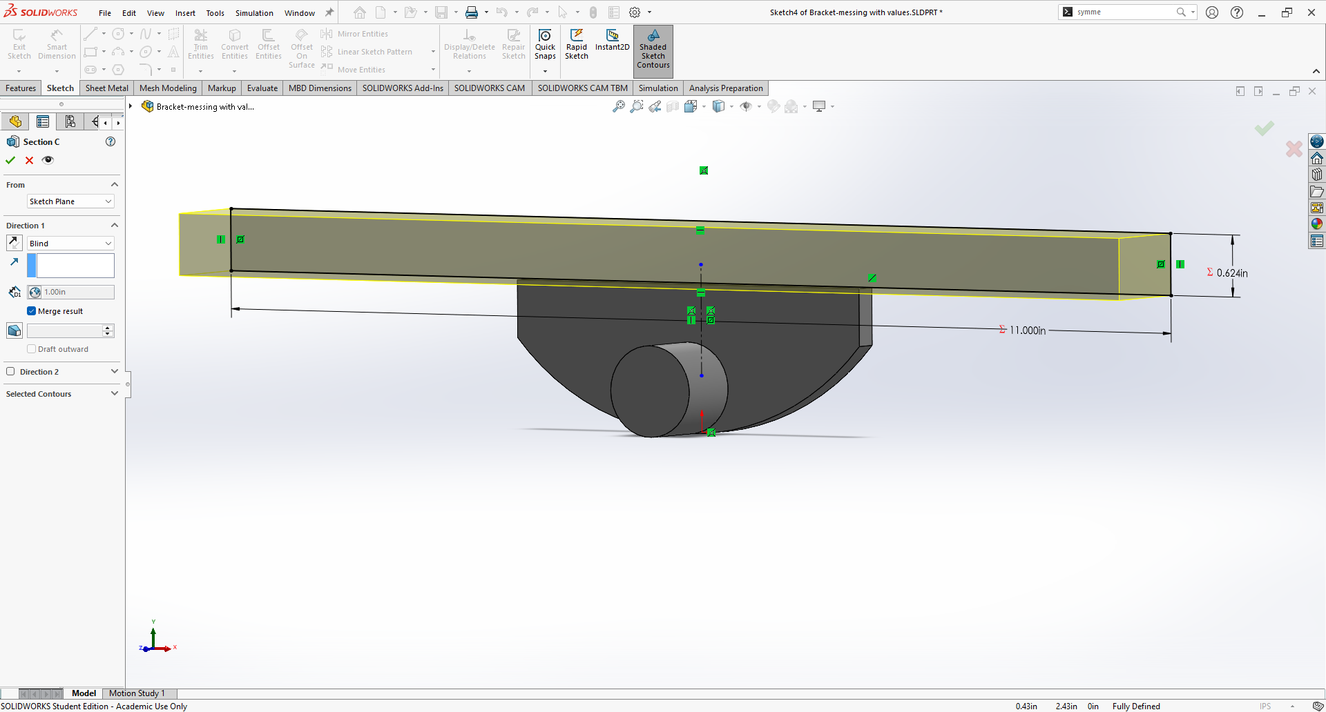
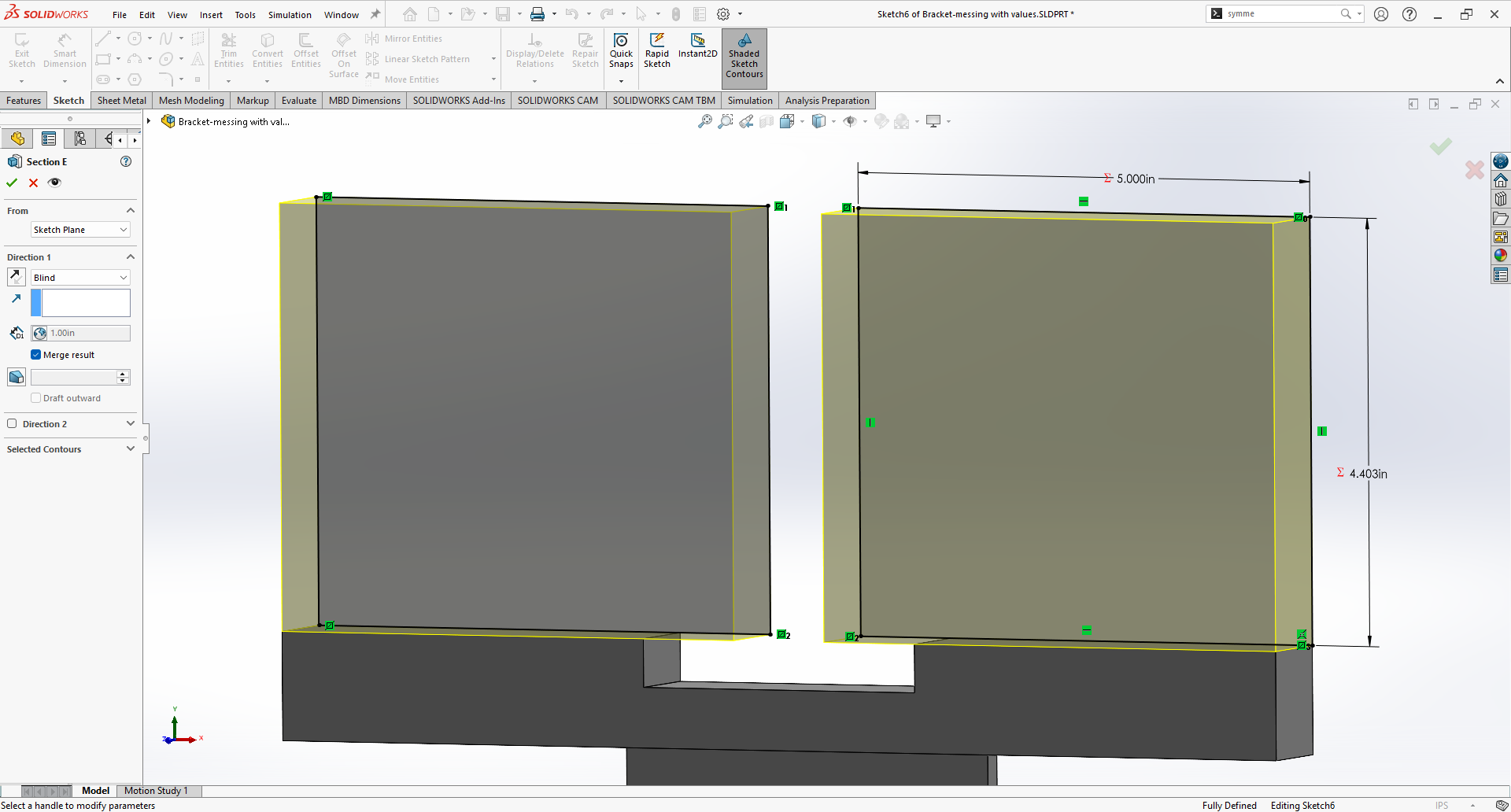
As you can see from the model geometry, every single dimension is attached to a global variable or equation from the values I input earlier. This means that if I want to alter the geometry of the part, I can edit the variables in the equation tab and the model will dynamically update to the new geometry. This is important, since I eventually come back to edit some of the dimensions later in the process.
Drawing Setup
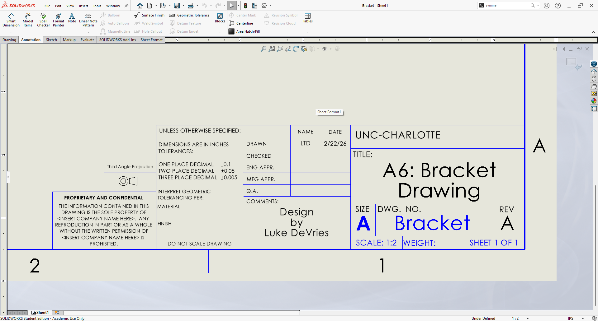
The first step for the drawing was to create the necessary title block and update it to reflect the part I was going to model. This includes the angle projection symbol, title, revision, author, date, tolerance block, and other sections. The SolidWorks template already comes with a well defined title block, but I customized it by removing the assembly blocks and other irrelevant sections for this project. I also had to add in the projection symbol for third angle projection and then filled in the remaining blocks with their correct information.
*While creating this ePortoflio page, I realized I forgot to add the material in the title block. I went back to update the drawing and also updated the revision block. The most up-to-date drawing pdf will be downloadable at the end of this page.
Drawing and Tolerances
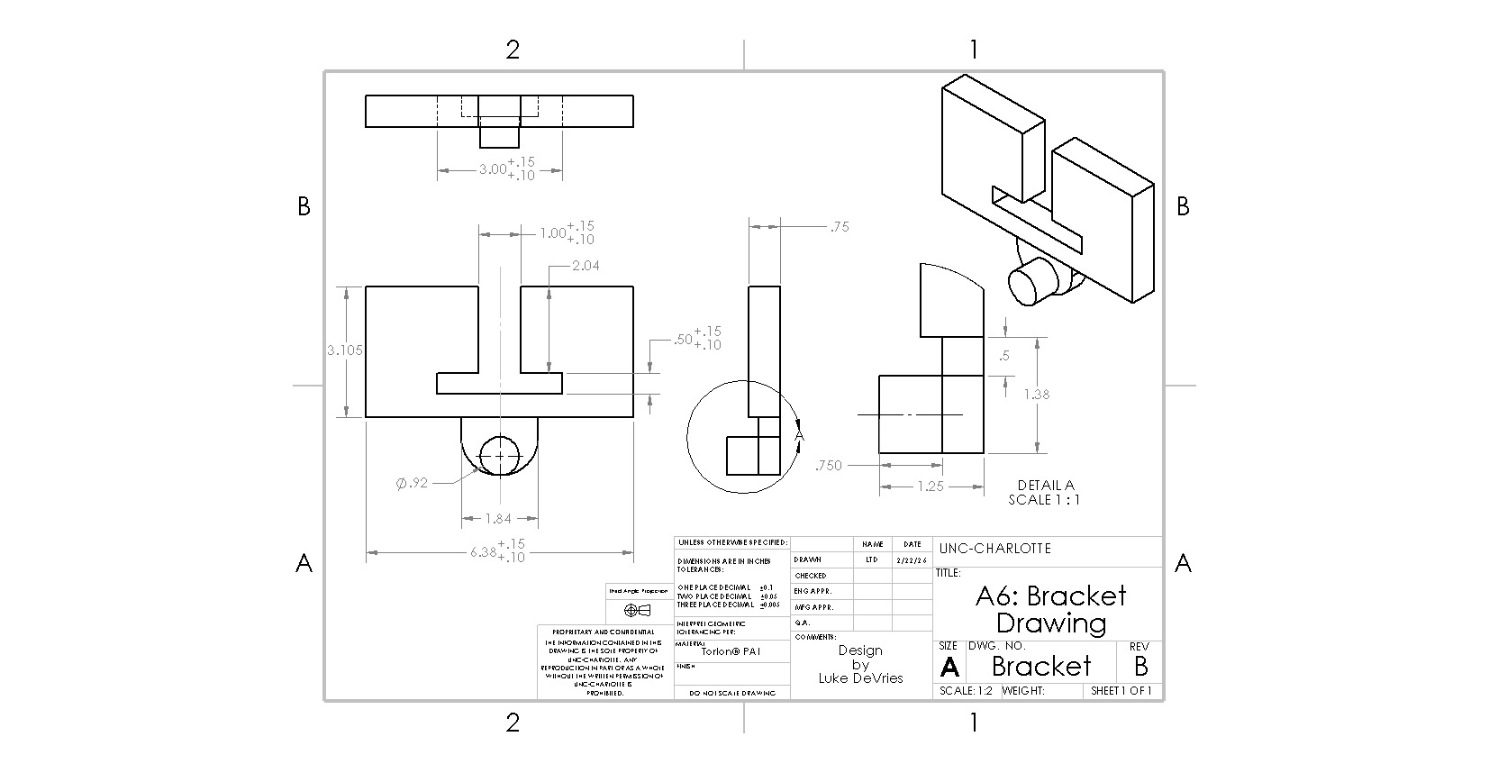
Since I utilized SolidWorks for both the part and the drawing, the process of adding the model views was quite simple. The process was as simple as dragging and dropping my isometric view into the top right corner, positioning the front view near the bottom left, and then using SolidWorks alignment to position the top and right views in their proper locations relative to the front view.
This assignment also asked that students include at least two additional line types to our drawing. I chose to include a symmetry line, which is seen on the front view, and a section view, which is seen on the right view.

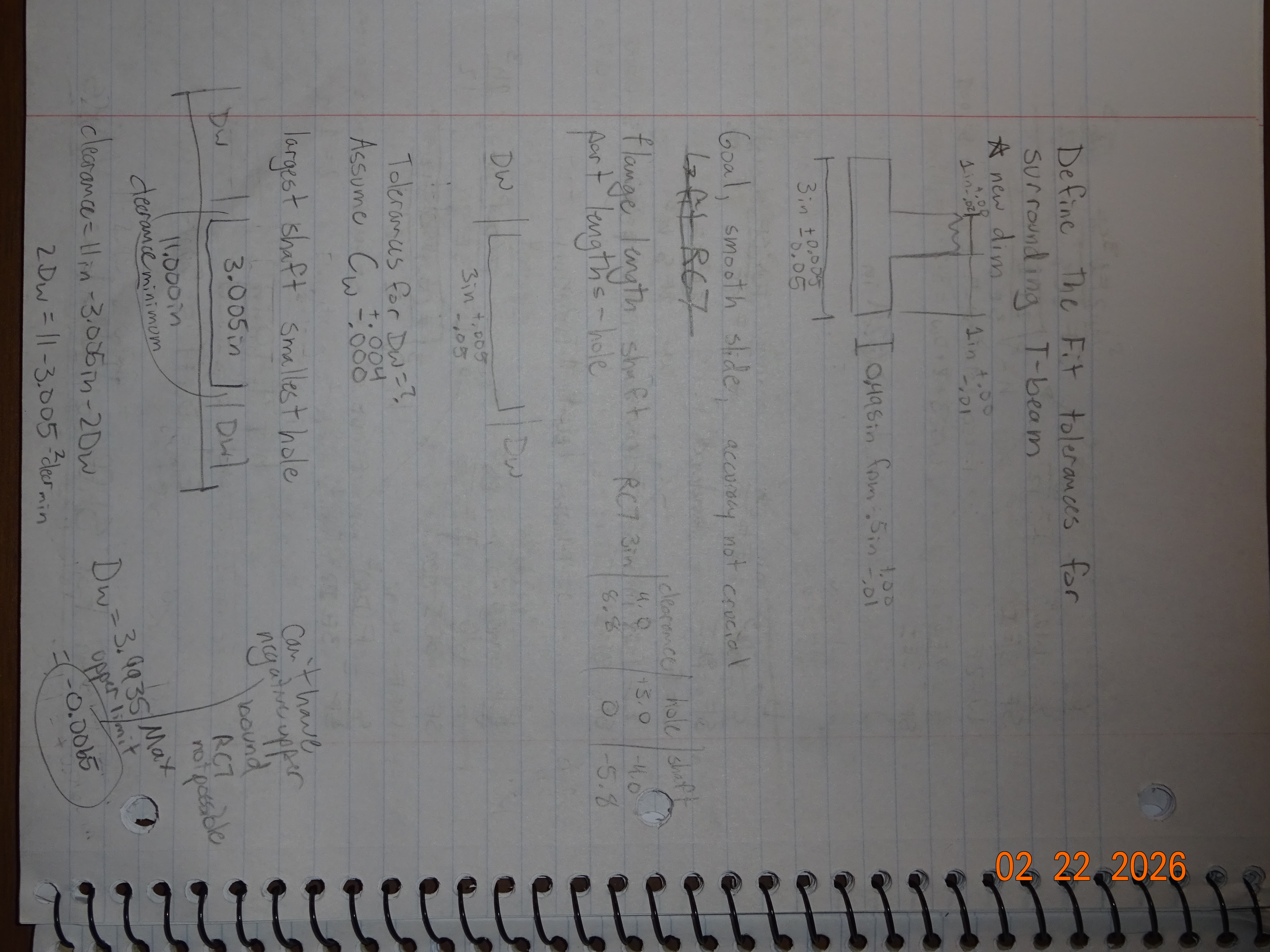
Adding the dimensions was not difficult, but did become complicated very quickly. The dimensions on the drawing were driven by my parametric model, but what I had to do was choose which dimensions I needed to include on the drawing and what tolerances they needed. I made this process a bit more challenging when I redid the dimensions with zero clearance in relation to the T-beam. I first wanted to add my tolerances based on one of the ANSI standard fits. The assignment calls for a loose sliding fit where accuracy is not crucial, which matches closely to the RC7 fit.
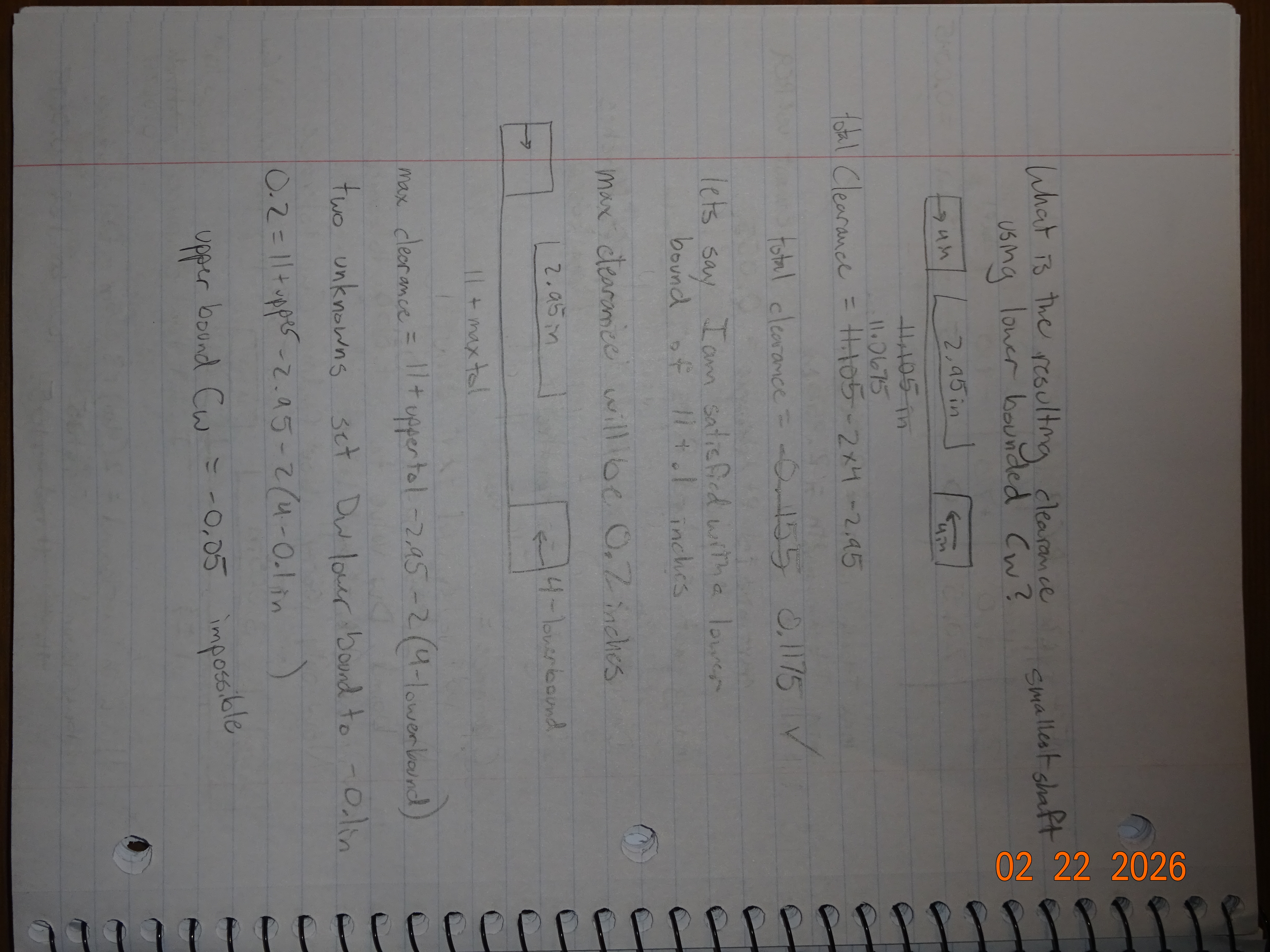
I tried to start using the specifications for an RC7 fit, but quickly ran into issues when my upper bound tolerance for the width of section C was a negative tolerance. This plus the specified tolerance of the T-beam being outside the bounds for the shaft in an RC7 fit made it impossible to dimension from this standard size.
I reviewed the other standard sizes and realized that the RC9 fit would also match the assignment description while having larger clearance and tolerance bounds. I thought that this could solve the issues I ran into with the RC7 fit tolerances. Before doing too much work, I checked the specified tolerance range for the shaft of an RC7 fit and quickly realized that the T-beam still had a much larger tolerance range. At this point, I figured that I needed to move past the standard fits, since the tolerances I was given were far from the standard fit clearances.
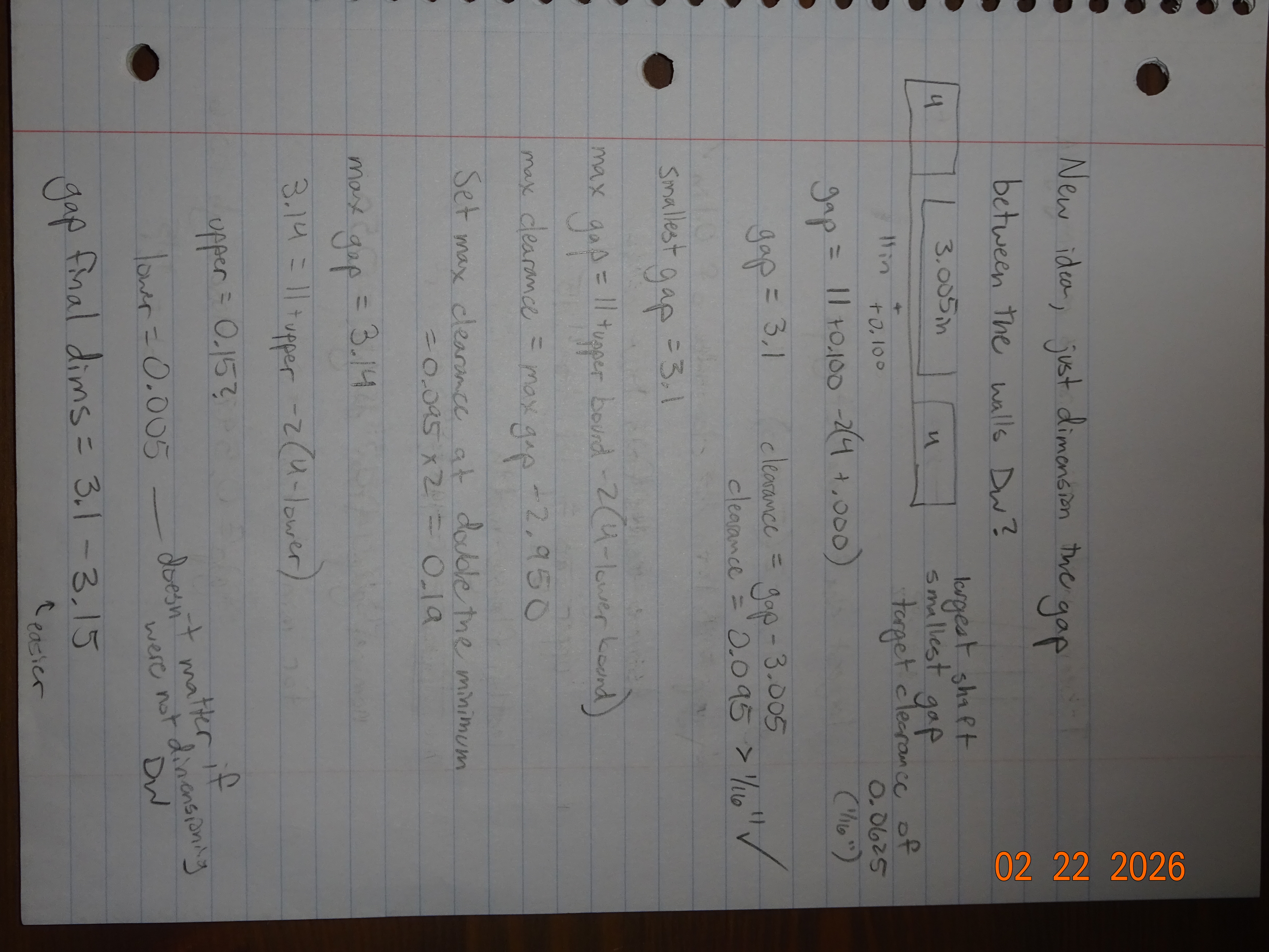
During the calculations for RC7 and RC9 fits, I was repeatedly running into trouble with compounding tolerances from the width of C and the width of both section D's. I decided to take a different route as I moved away from the standard fit tolerances. I began by limiting my D widths to a + nothing tolerance and focusing instead on the width of section C and the gap that the T-beam flange slots into. I set a reasonable total minimum clearance for the T-beam flange length at 1/16 inches. This meant that ideally, there could b a gap of about 1/32 inches on either side of the T-beam flange when the bracket was on. This did heavily rely on a bilateral tolerance of +/+ on my C width. This comes back to my most recent dimension calculations which left no pre-clearance between the bracket and the T-beam which has an upper bound for the flange length. I decided that I would have to settle with two positive bilateral tolerances, and continued to solve for the lower bound of section C's width.
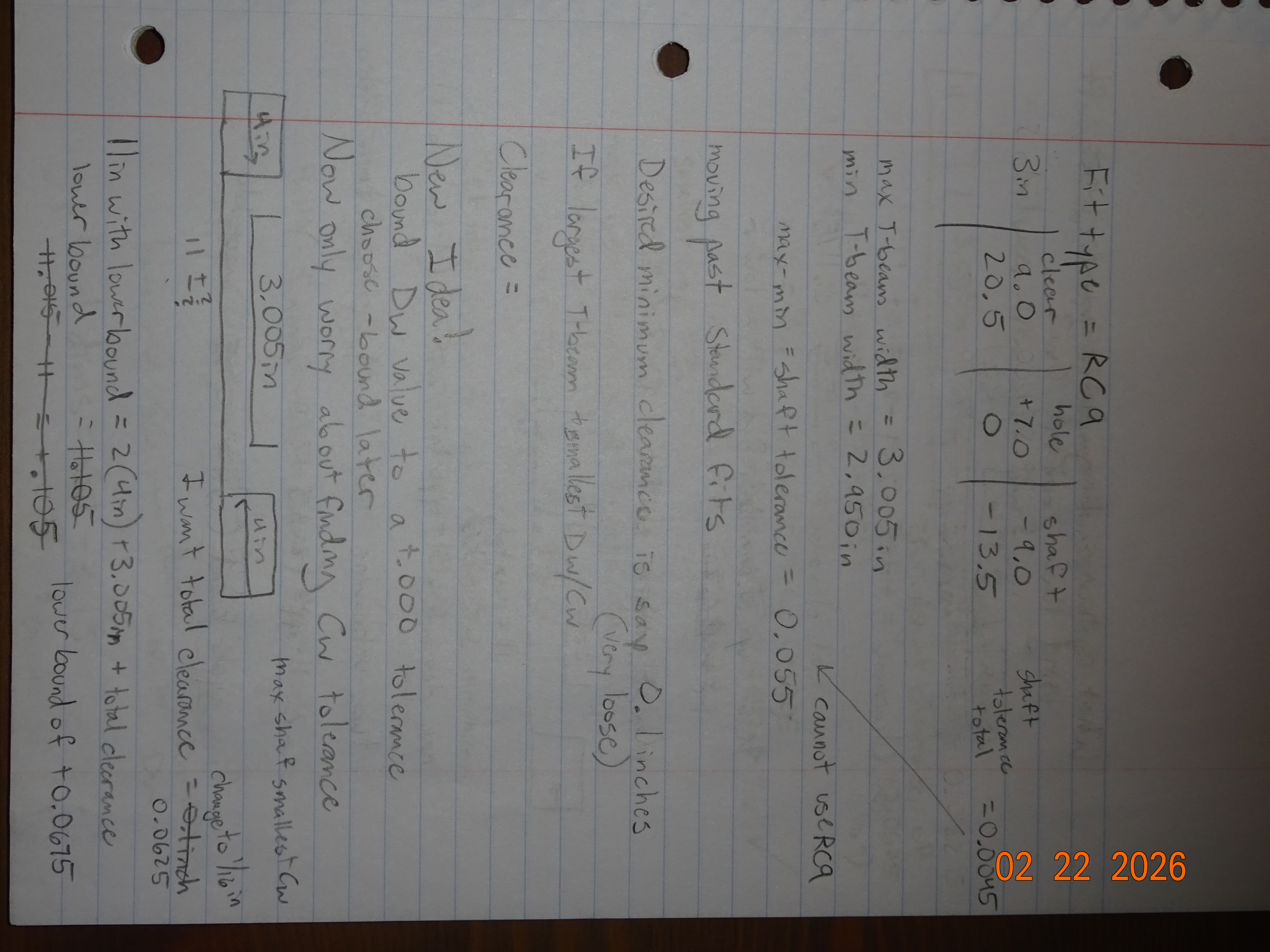
Ultimately, I was able to get the desired minimum clearance with a lower bound of 11 +0.0625, but for simplicity I decided to round that tolerance to 0.1 inches. I also found what the lower bound clearance would be with the lower bound of the T-beam, and found that it yielded another acceptable clearance around 0.1 inches. Next I moved to setting an upper bound for the C width. At this point, I still tried to see if I could account for a lower tolerance bound on the section D width, but by accounting for both sides and their tolerances, I was not able to get tolerances that would fit a maximum clearance of 0.2 inches (double that of the minimum clearance). This was frustrating to say the least, so I took a moment to think about why I needed to find these tolerances and how the drawing was supposed to aid the creation of the part, not the design of the part.
The lab section of this class, MEGR 2156, has students working to create an air engine from engineered drawing in a machine shop. I realize that this bracket is being designed out of a plastic polymer, but I believe that the manufacturing thought process stays the same. The dimensions and tolerances given for the machined parts gives all necessary dimensions for machining, not for designing. What I mean by this is that rather than being given the tolerance for the distance between diameters of a hole on round stock, we are given the diameter of the hole. This seems very straight forward, especially for a hole and shaft design with fits, but I believed I could apply this strategy to my tolerances and dimensions for the bracket. I did not necessarily need to define the width and tolerances for section D's width, but rather I could specify the resulting gap between them and give that value a tolerance. I would still have to design around the compounding tolerance from section C's width, but I could essentially bypass the tolerance of Section D's width and rely on the safety factor to protect the dimension if the gap resulted in a smaller than desired width. This made my calculations much simpler, and I was able to come to a final range for the gap dimension.
I had a final gap range of 3.1 to 3.15 which adhered to the minimum and max clearances I had set earlier of 0.1 and 0.2 inches. From here, I would later use the driven gap dimension from the model and add the bilateral tolerance bounds that would yield my desired gap dimension range.
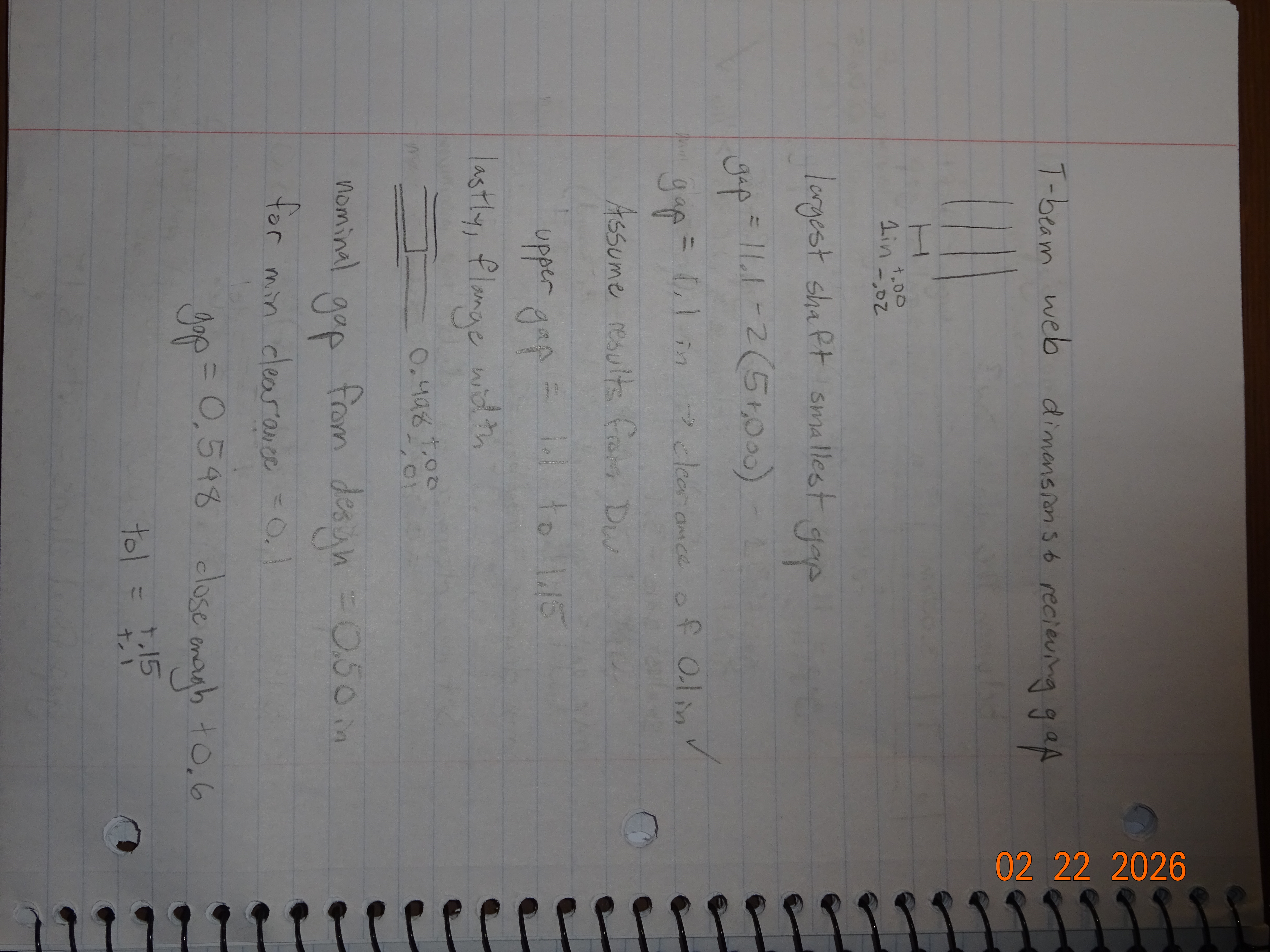
The last tolerances I need were for the T-beam web width and the T-beam flange width. I used the same approach as the previous tolerance and abided by the same minimum and max clearances. The T-beam had a + nothing tolerance for both of these parts, which meant I realistically had a little more liberty with the tolerances, but my calculations came out close to the same as for the flange length, and so I decided to reuse the same rounded but satisfactory tolerances for the other gaps around the T-beam.
This meant that were the bracket design to be manufactured, the important dimensions for creation would be the sizes of the gap where the T-beam fits into the bracket as well as their tolerances which yield the desired clearance. This is a much better approach for giving dimensions than trying to list out the designed dimensions from the model. Additionally, the safety factor of 4 should cover any small reductions in size that would come from the tolerances I added.
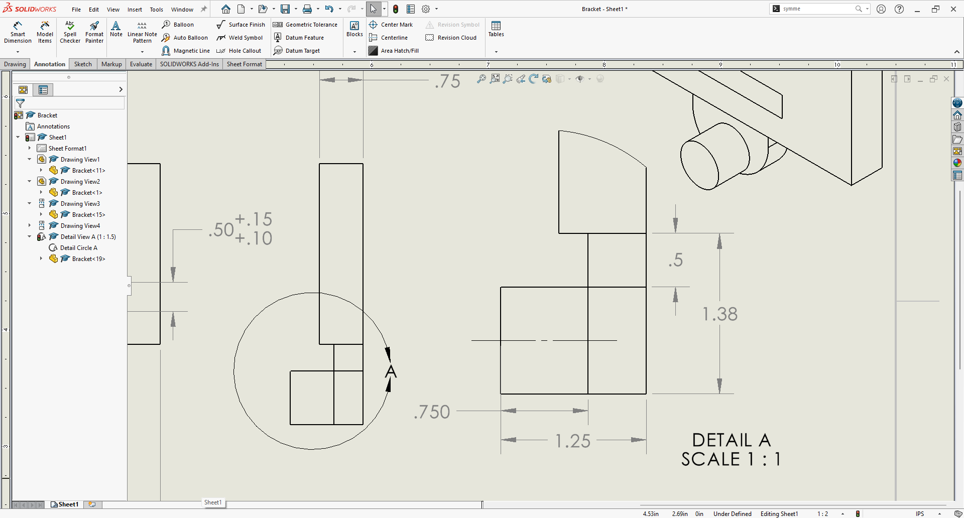
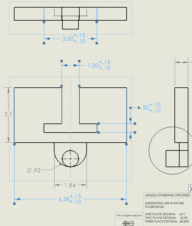
Finally, I was at the point where I could finish up the dimensions and tolerances of my drawing. Previously, I had added all the less precise dimensions with basic tolerances, and all that was really left were the gap dimensions and tolerances. Below is an image showing how all the gap dimensions share a common tolerance of +.15/+.1
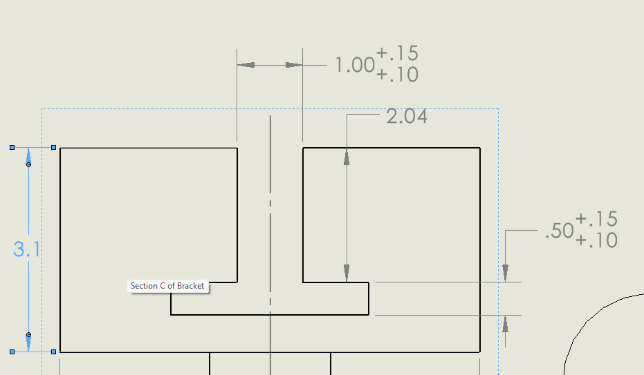
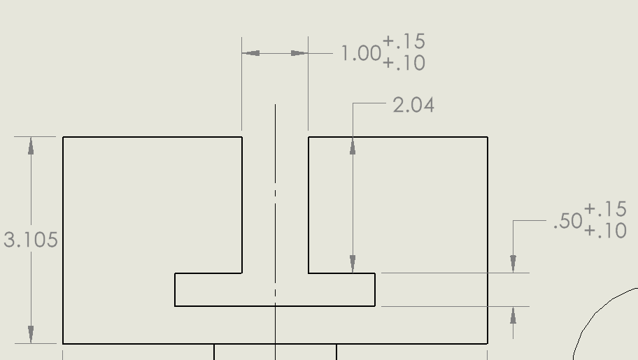
While I was focused on tolerances, I noticed an oversight that I had made in my so-called "less precise dimensions." I had given the overall height dimension of the bracket a very high tolerance, but I realized I should check to make sure that my upper bounded gap tolerances would give enough space to the lower limit of the overall height. I checked and it reduced my designed C height by over 50%! The safety factor in the design could theoretically cover this reduction in height, but this did not feel right to me. Instead, I increased the precision of the dimension to move it into a higher tolerance specified in the tolerance block. This still resulted in a worst-case scenario reduction in the height of section C, but it was less than a 50% reduction which made me feel much better. The image on the left is the less-precise height dimension subject to a tolerance of +/- 0.1 inches originally, and on the right is the new more precise dimension that has a tolerance of +/- 0.005 inches.
Part Modification
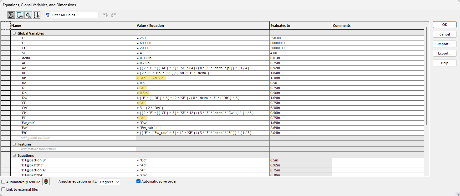
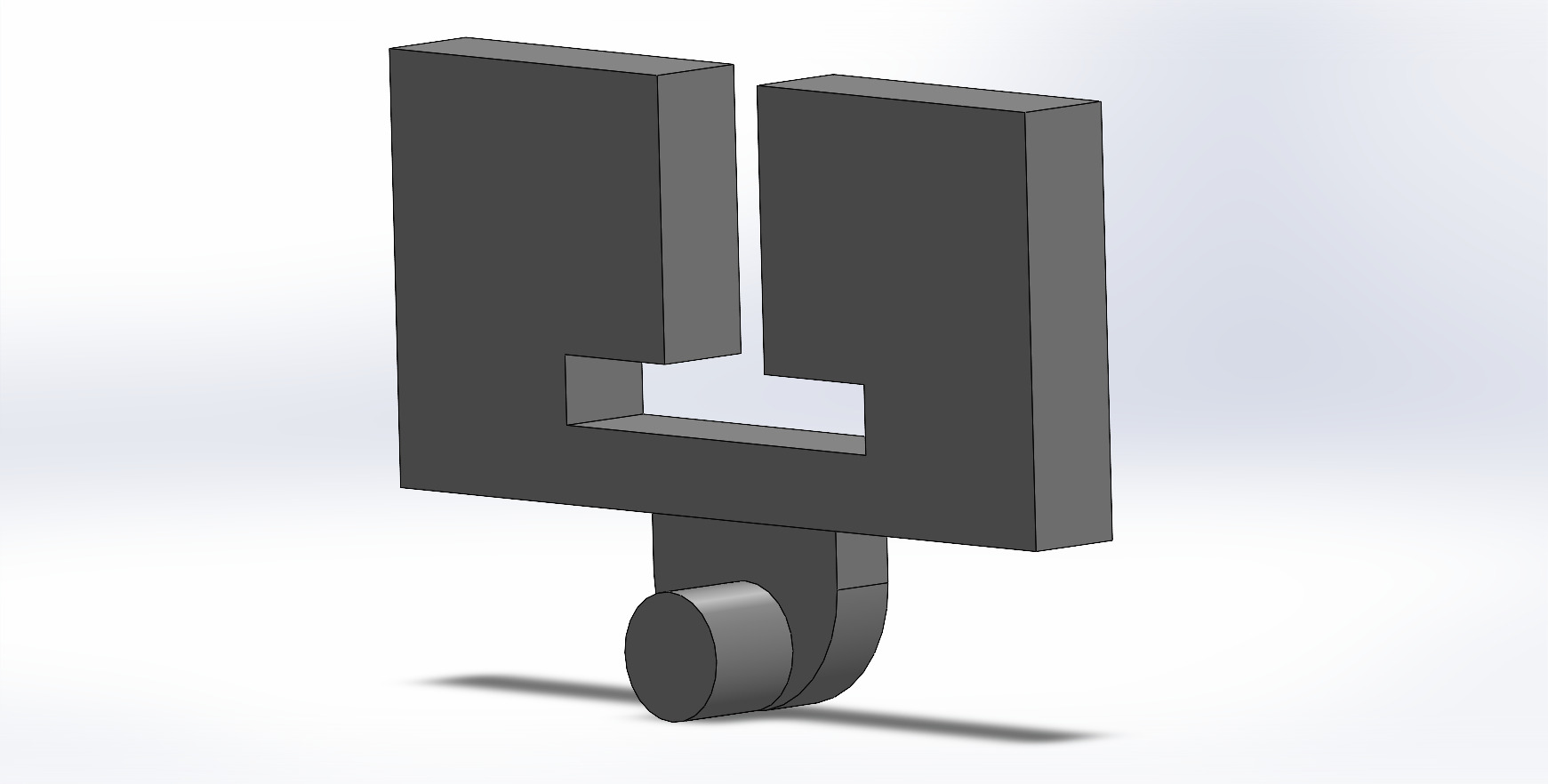
Before I show the final drawing, it may be obvious that the dimensions in the back of the previous section do not match what I calculated at the beginning of this process. This is because I was ultimately unhappy with the aesthetic look of my bracket. I realize that this is not at all a high priority for the design, but now that I had my tolerances set, I could go back to the model and update the geometry to look a little nicer. I primarily cleaned up the dimensions of the bracket by making changes to the side profile and tweaking how certain dimension relations were defined. I used the equations to identify which values would yield the results I was looking for which was a smaller width and height for the bracket. The symbolic representations were helpful for finding these driving dimensions, and I was able to test a few different values before coming to the final dimensions. Below will be an updated image of the equation tab for the model followed by a screencapture of the final bracket which I think looks much better than my original dimensions. (For reference, my original C width was nearly a foot long whereas the new C width is only ~6.5 inches. Nearly half the overall size!)
Finalizing the Drawing
Since the drawing and model were linked through SolidWorks, my drawing was updating dynamically with the part. The new dimensions were good enough to even reduce my original scale of 1:4 down to 1:2 on A sized paper. I was satisfied with the look of the beam, so I did one last check to make sure that I had all necessary dimensions to create the part. The process I used to check that I had enough dimensions was to go back through each section and make sure that the section's geometry was either directly dimension or accounted for in another dimension (e.g. The total height of the bracket accounts for the height of C,D, and E while the gaps define their individual heights). Each of the 5 sections looked fully defined in the drawing, and I was happy with the dimensions I chose to provide from the perspective of someone who might be trying to create the bracket. Below is an image of the final drawing, and a pdf download is available at the end of this page.
Downloads:
- Hand-written work pdf file here.
- Bracket CAD model sldprt file here.
- Bracket Drawing slddrw file here and pdf file here.
Lessons Learned
I learned a lot about the practical reasons for creating a parametric design, as well as the importance of tolerances. I also learned the hard way that fits are more difficult than I anticipated, especially for non-standard geometry and tolerances. The parametric design in this case was crucial for me to come back and edit some of the calculated relationships and driving values to get a form factor that I wanted for the final bracket design. The tolerances also allow the T-beam to have the smooth sliding clearance that was asked for in the assignment description. Without the tolerances, my bracket would have been way too tight, even at the minimum tolerance bounds for the T-beam, so it was a necessity to have good tolerances for the gaps in the bracket. I think that with a little more foresight, I would have been able to design the bracket in a way that allowed standard fit clearances and tolerances, but working through the complications I ran into allowed me to reach a result that I believe is better than if I had stuck to using a standard fit.
Overall, I was able to get a better understanding of what Engineering Drawings are and the ways that they differ from the 3D model. The main difference that I identified was which dimensions are being provided with the part. My drawing includes dimensions that are not visible in my 3D model, but they still have to fully define the part. This was the biggest challenge that I didn't initially expect. It is important to be concise with the dimensions you give to the part while still giving enough detail to fully define its geometry. My model and drawing are far from perfect, but throughout the process of this assignment, I could see a lot of improvement from what I started with and from what I originally thought the model and drawing would look like.
Time Spent
In total, I think I spent a little over 10 hours on this assignment.