
Gear Box Design
Assignment Objectives
- Design a gearbox that can be assembled and disassembled.
- Analyze and size input and output shafts for strength.
- Design journal bearings to support shafts.
- Create a gearbox housing with proper clearance and fastening.
- Use parametric CAD modeling to generate a final design.
- Document calculations, sketches, and lessons learned.
Assignment Description
Design a gearbox which can be assembled and disassembled. The spur gears have a gear ratio of 24:9 and are listed in the resource section. The output gear torque and speed are to be 1.25 in-lbf and 1100 rpm relative. The input (pinion,power-transmission) and output (gear, short shaft) shaft diameters are .125 and .25 inches respectively and each have a length of 1 inch. Use the appropriate equations in the Machinery’s Handbook for empirical units. The critical features of the gearbox include the shafts, and the journal bearings.
Assumptions
- Assume appropriate strength of shafts, use Machinery’s Handbook.
- The gear train is ideal.
- The moment of the radial force from the gear train is small enough to be ignored.
Notes
- The shafts are press fit through the hubs of the gears.
- Make sure there is enough clearance between the gears and the gearbox.
- Use a running sliding fit for the size of the hole for the shafts.
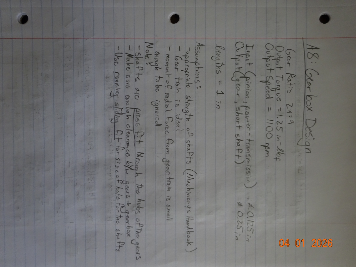
The first thing I usually do for each assignment is copy down most of the important assignment information. Below is an image of my first page of work.
Design of the Shafts
The first step for this gearbox required students to verify that the shaft diameters would be sufficient for output speed and output torque from the given gear ratio of 24:9.
Input shaft :
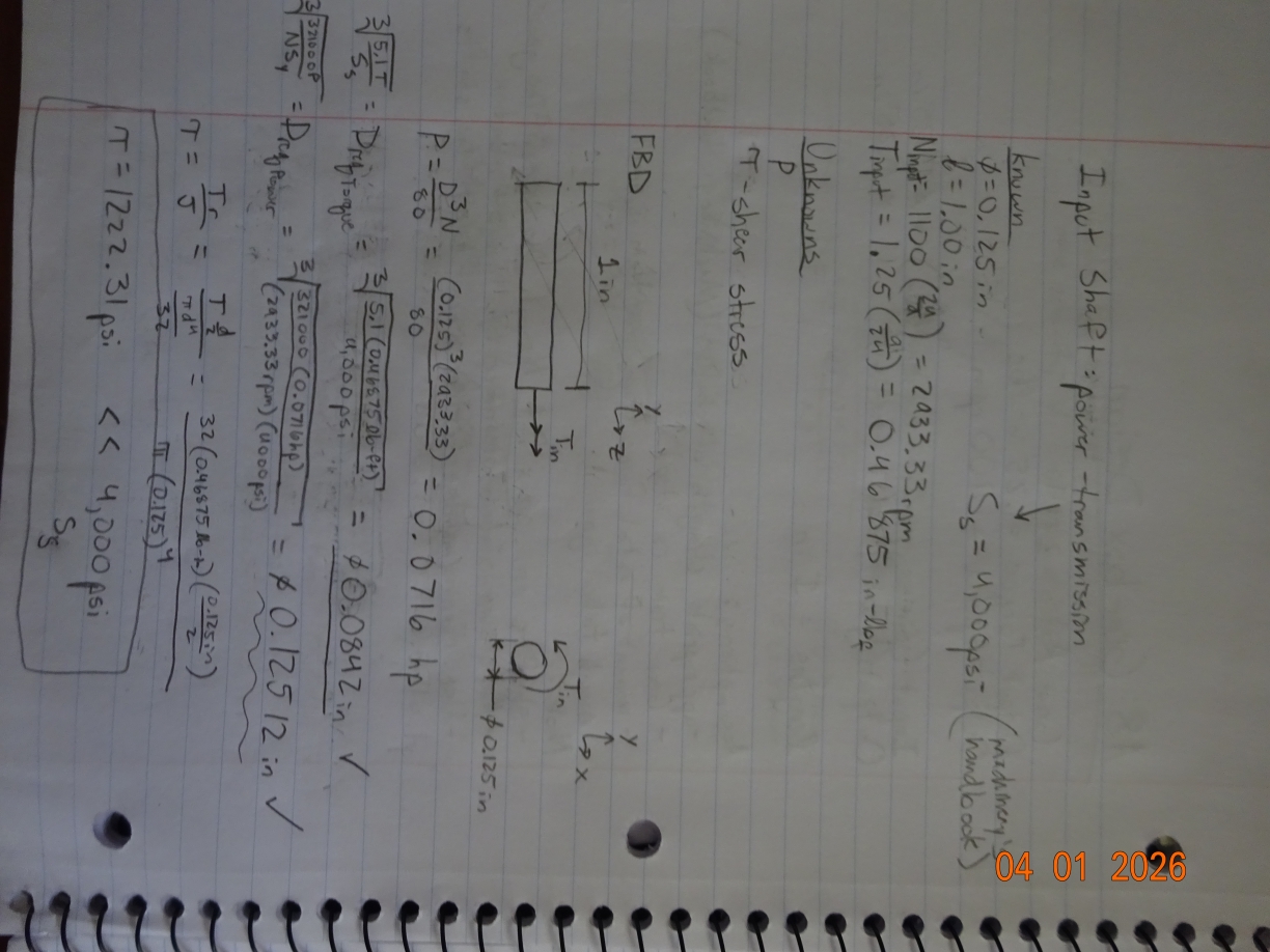
I started with the input shaft which was defined as a power-transmission shaft. First, I made sure to use the gear ratio to calculate the input speed and input torque to use for the following calculations. I was able to use the Machinery's Handbook to find the necessary equations get the power through the shaft in horsepower. With the power calculated, I was able to solve for the minimum required diameter in two ways, one dependent on the torque in the shaft and the other dependent on the power and speed of the shaft. These equations both required the use of a standard max shear stress which was 4,000 psi for a power-transmission shaft. Both of the minimum diameters were at or below the given 0.125 inches, so I can be confident that the input shaft will be sufficient this application. I also calculated the shear stress within the shaft and found that it was well under the maximum shear stress provided by the handbook. My work is shown in the image below.
Output shaft :
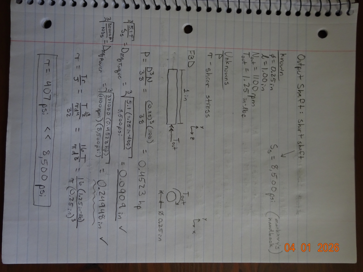
The output shaft was defined as a short shaft, and so I had to use a different maximum shear stress of 8,500 psi for the output. I also needed to use a slightly different power formula, but the process was the same. I solved for the power, found the minimum diameter from both the torque load and the power/speed of the shaft, and found that both were at or below the given 0.25 inch diameter. This was enough information to be confident that the output shaft would be sufficient for this application. I also chose to calculate the shear in the shaft and found that it was well below the maximum shear stress provided by the handbook. My work is shown in the image below.
Design of Journal Bearings
The next step was defining and selecting the journal bearings that I would be using for the gearbox housing.
Material Selection:
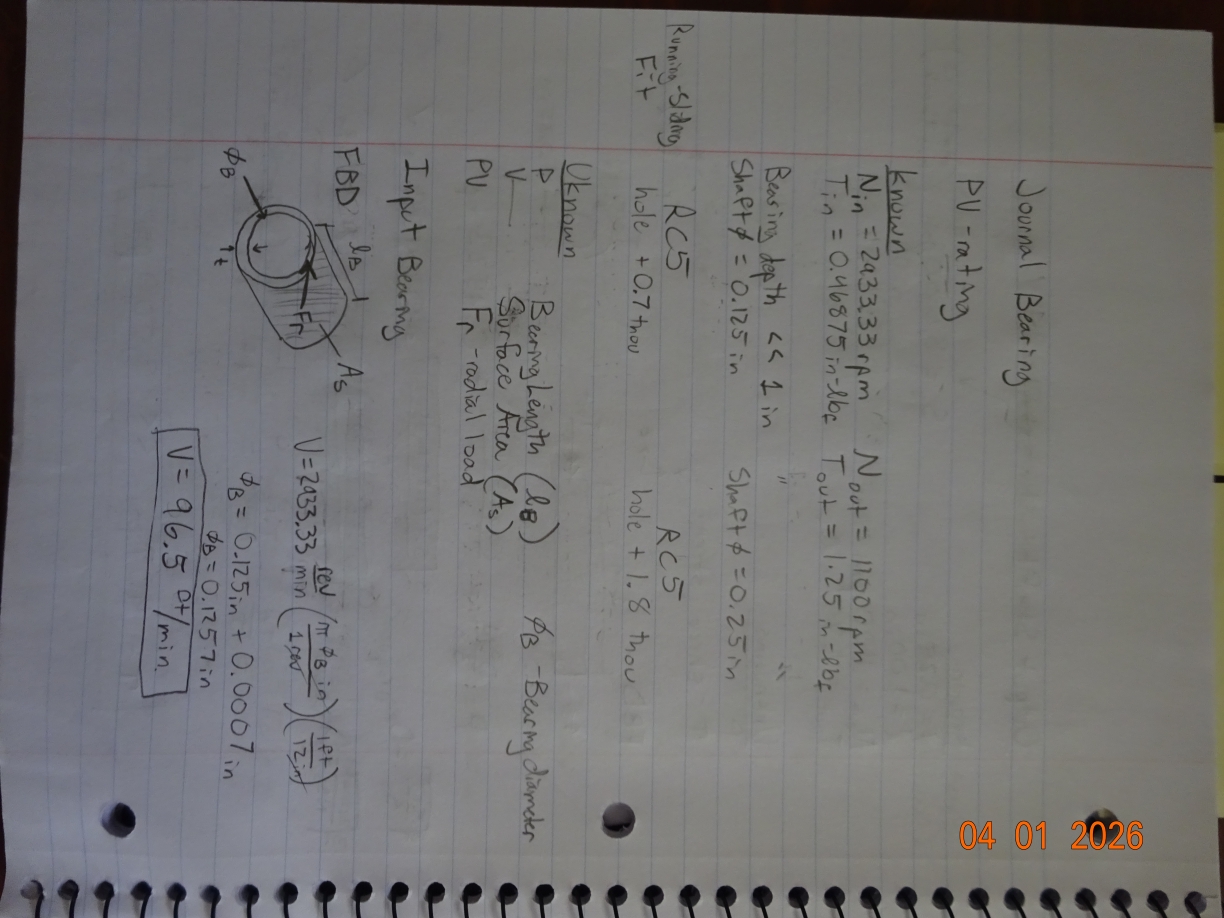
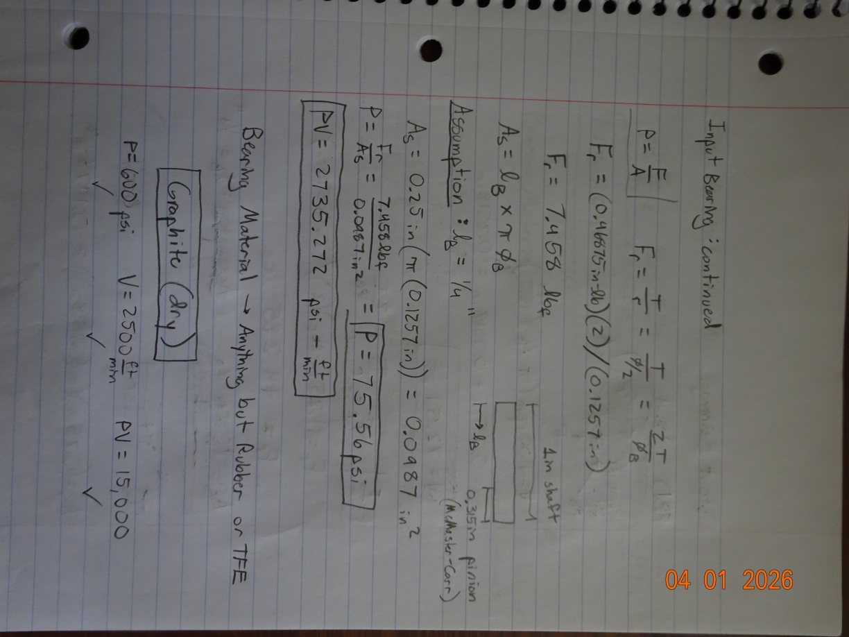
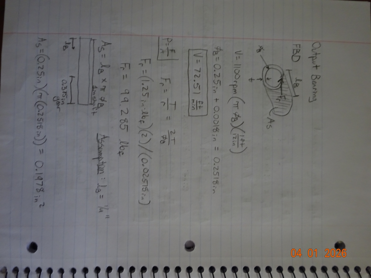
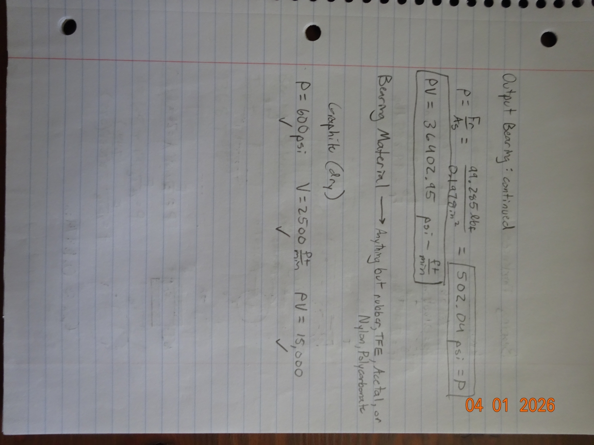
The first design criteria to be found was the material for the bearing. To do this calculation, we needed the P, V, and PV ratings for the journal. The velocity calculations were simple, being only a conversion from rpm to feet/min, but the pressure required calculations using the radial force from the torque and the surface area of the journal. To find the surface area, I made the assumption that both of my journals would be 0.25 inches. I got this value by taking the 1 inch shaft and subtracting the full gear width (with hub) and then choosing a value that was roughly half the remaining shaft length. This would ensure that I have about a quarter inch at least remaining for the shaft that protrudes out of the housing. The other value needed to calculate my bearing pressure, was the bearing diameter. The assignment mentioned that the holes for the shafts should use a running sliding fit, so I quickly checked which fit class would be best for this use case. I settled on RC5 for the fits, since it should give amply clearance for the shafts to rotate while also being tight enough to avoid any unwanted movement of the shaft within the bearing. I found the hole tolerance for the 0.125 inch shaft to be +0.7 thousands of an inch and the tolerance for the 0.25 inch shaft to be +1.8 thousands of an inch. I added these values to the nominal shaft diameter to get my bearing diameter for the calculations. From there, I simply calculated the pressure as force over surface area and found PV as well. Both bearings left me many acceptable materials, but I chose the Graphite (dry) material since it worked for both and seemed to offer decent head room above my calculated values. My calculations for both the input and output journal bearings are shown in the images below.
Bearing Thickness:
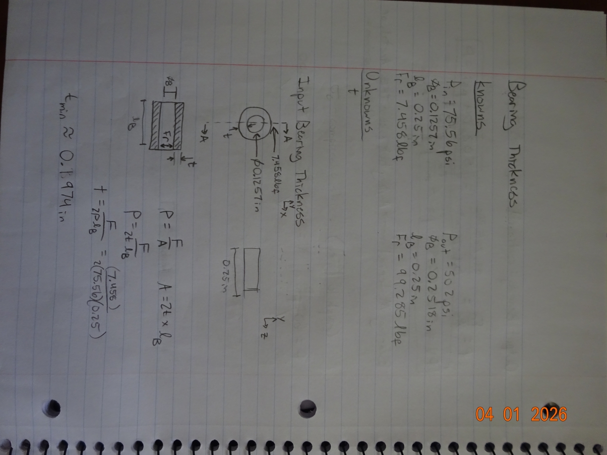
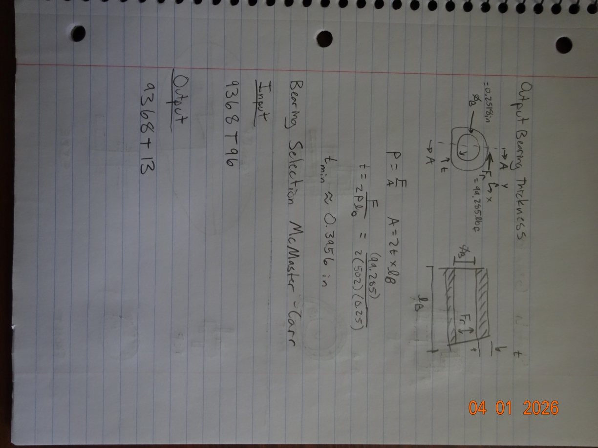
The bearing thickness calculation was a bit confusing to me, and this step alone took me at least an hour to think through and trouble shoot before coming to a final model to calculate the thickness. I chose to use the formula for pressure/axial stress where the force was still the radial force from the torque, but the area was the cross-sectional area of the journal bearing along its center axis. This may not be the ideal model to calculate the bearing thickness, but in both cases it got me a reasonable bearing thickness to look for as I selected my bearings. The work for the thickness calculations are in the images below.
Note: the thickness for the output shaft was a fair bit larger than the input shaft, and I was unable to find a real-life bearing with that thickness for the other dimensions I wanted. I suppose it would be possible to have redefined my bearing length to lower the thickness and find a suitable real-world bearing, but instead I simply looked for the largest thickness bearing with the length I had already defined.
Journal Bearing Selection:
The final step for the journal bearings was to select the real-world hardware from McMaster-Carr. As I mentioned in the previous note, I was not able to find a journal with the thickness I calculated for the output shaft, so I instead selected the bearing with the largest thickness I could find at the bearing diameter and length that I had defined for myself. This ended up being an output journal bearing with a thickness of only 0.126 while I had calculated 0.3956 for the minimum thickness. I acknowledge that I made this selection despite my calculations, and I believe that a better selection could be made by altering the assumed bearing length to be longer than I utilized. With that being said, my input journal bearing was selected to be a 9368T96 journal bearing which is a High-Temperature Graphite-Lubricated Sleeve Bearing made from Bronze. The output journal bearing was selected to be a 9368T13 journal bearing which is also a High-Temperature Graphite-Lubricated Sleeve Bearing made from Bronze. I downloaded the 3D models from McMaster-Carr to be used later in my CAD model along with the 48-tooth and 18-tooth gears provided from the assignment description.
Sketch Gearbox Housing Design
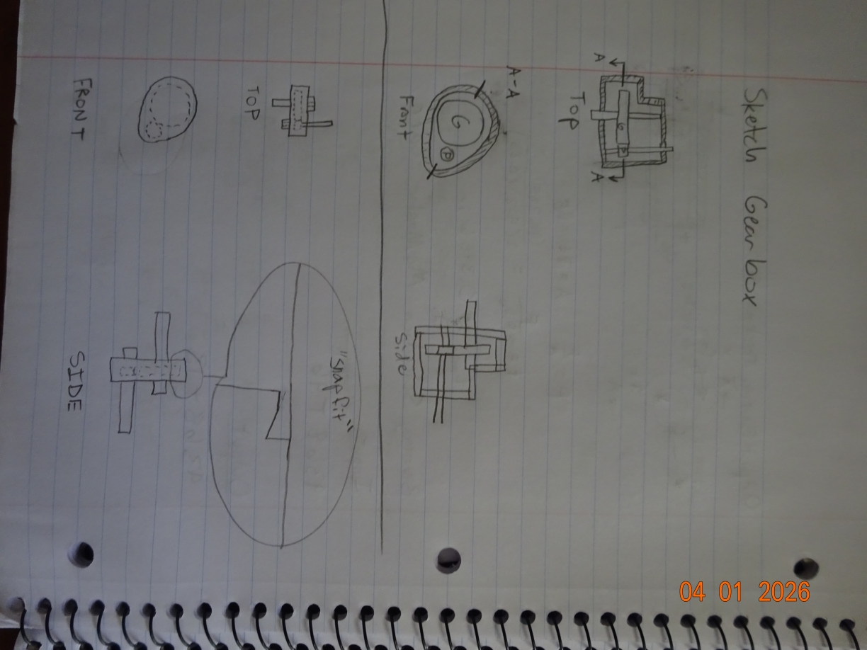
Before starting up SolidWorks to begin the modeling process, students were asked to sketch a rough design for the gearbox housing that included the position of the gears, the division point for the two sides of the housing, and a rough idea of the fastening design to close the box together. Below are two rough sketches I made, they were both drawn to have the housing split along the plane that is parallel to the face of the gears, and I had originally planned to utilize a snap-fit for the closure. Below is an image of the two sketches I made
Note: I later decided to switch to using bolts to fasten the two portions together as this was an easier design implementation that designing the snap-fits on the casing. The snap-fit may still be a good alternative to reduce hardware depending on the material of the casing, but due to time constraints I was not able to design the snap-fits.
CAD Model
Shaft Models:
The first parts that needed to be modeled were the two shafts. These models were by far the simplest parts, but during the assembly I decided that it would be nice to add chamfers to both edges since they are to be press fit into the gears. Here are some renders of the input and output shafts:
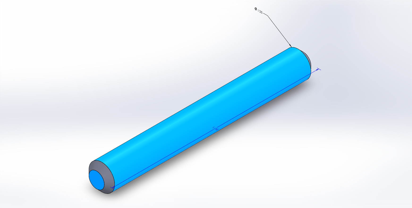
Input Shaft
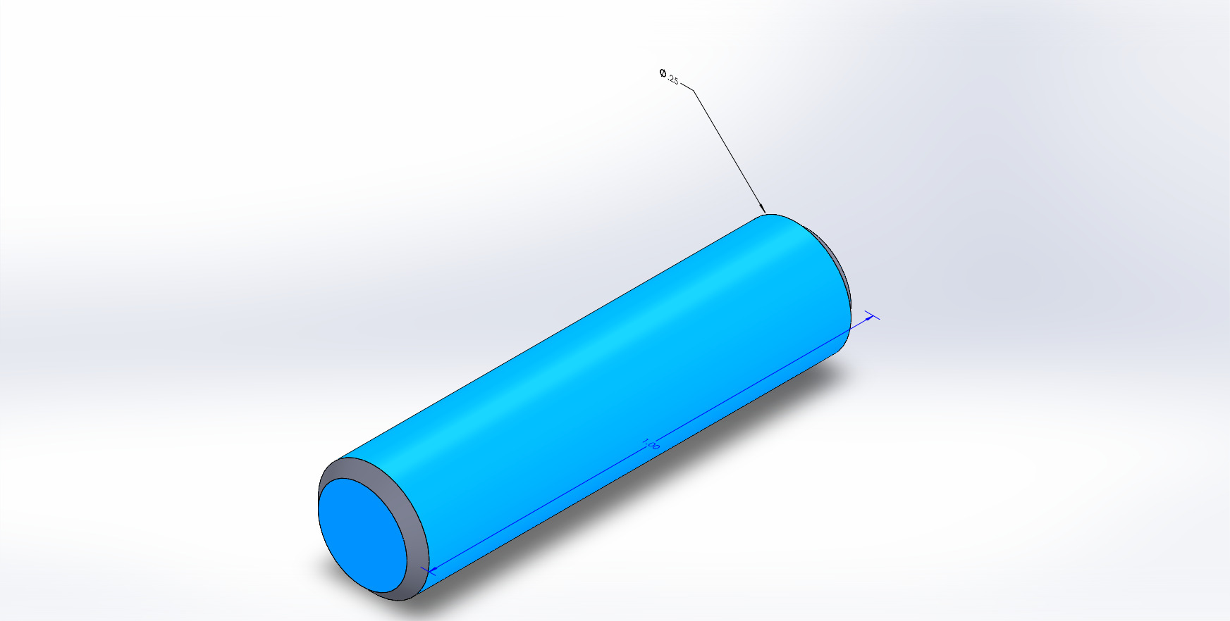
Output Shaft
Gear Housing:
The next task was the most difficult part, which was creating the first half of the gearbox housing. I will admit that I spent a good hour or so messing around with some designs that were derived from my sketches, but it wasn't until I took a break and came back that I knew how I wanted to design the housing. I started by working my way from the back/input side of the gearbox and working out towards the front/output side. Below I will include an image of the design step with some information about my choices and where certain parametric equations were used and what values they include.
Gear Housing Bottom:
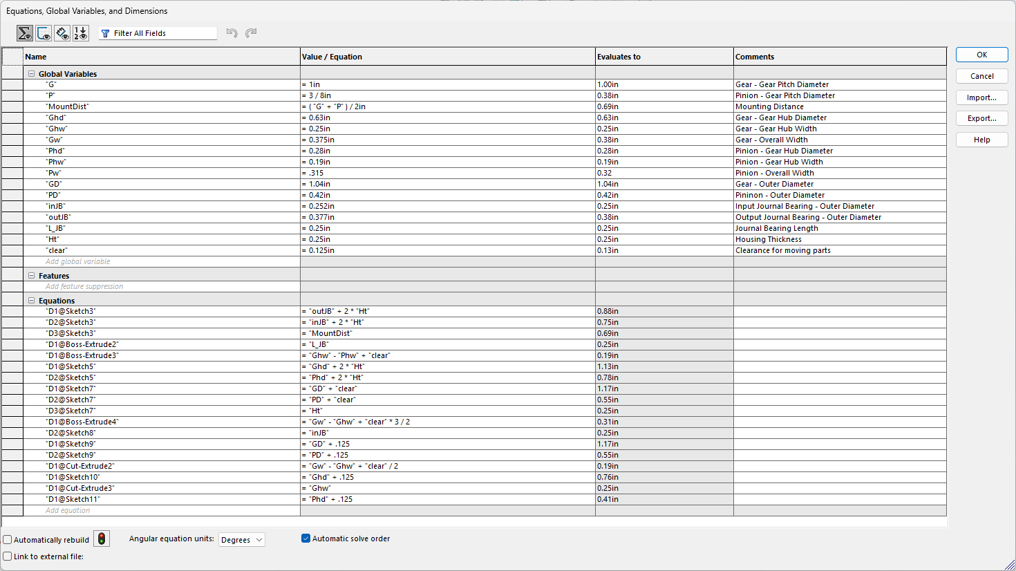
These are the global variables used for both halves of the gearbox housing models. This specific screenshot also captures the equations used for the dimensions of the "GearHousing_bottom.sldprt" file.
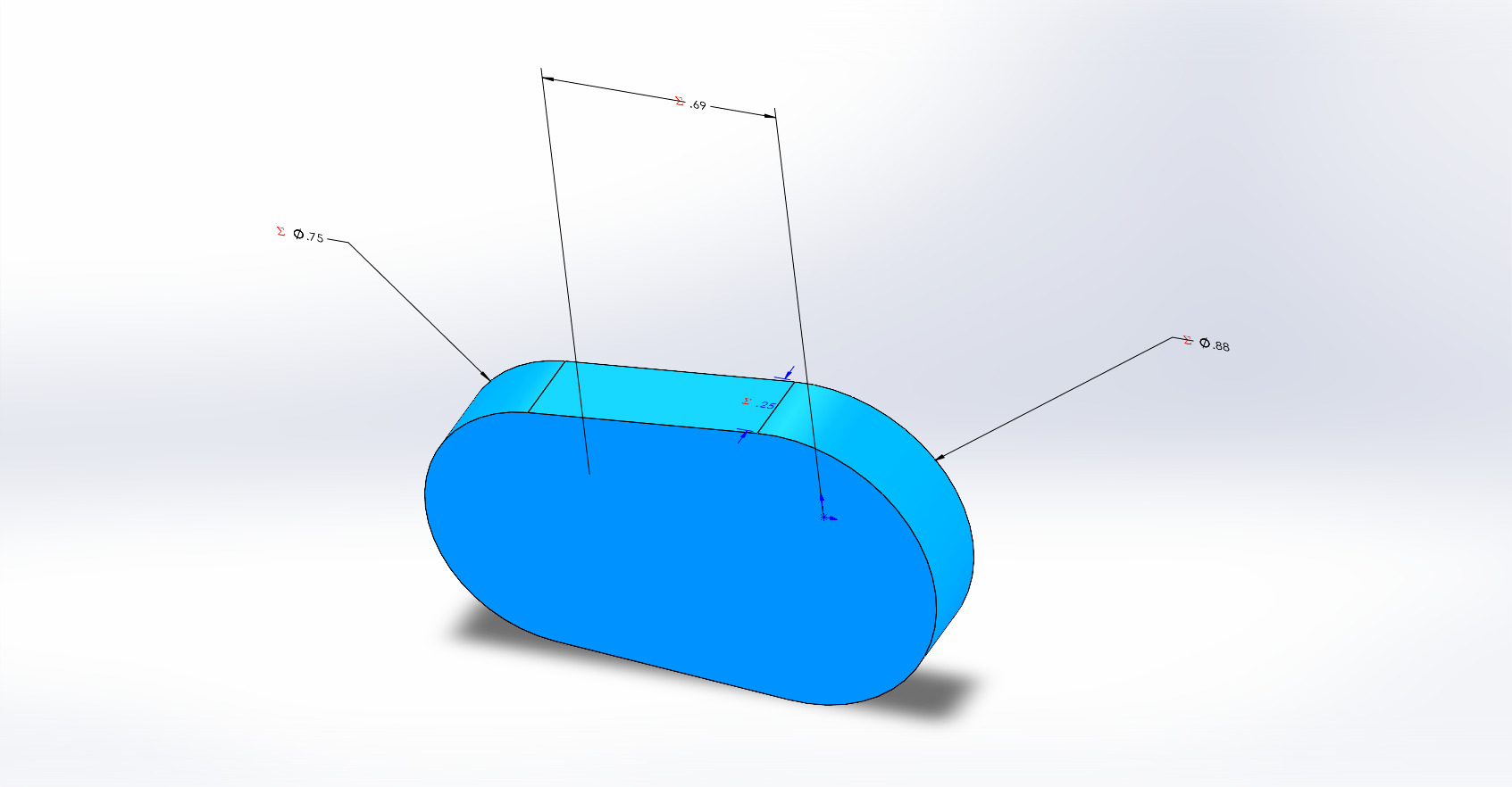
This is the first extrusion of the gearhousing. The size was defined first and foremost by the mounting distance for the two gears. From the end points of the mounting distance, i created two circles with diameters equal to the corresponding journal bearing diameter plus an arbitrary "housing thickness" of 0.25 inches. I then extruded it outwards to the bearing length.
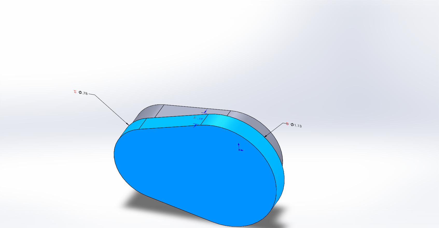
The second extrusion was the portion where the gear hubs would sit. I used the same method as the previous extrusion, but used the corresponding hub width's for the diameter equation again adding the housing thickness as well. The extrude was made to the length of the gear hub width - the pinion hub width + "clear" which I defined as an arbitrarily set clearance of 1/8".
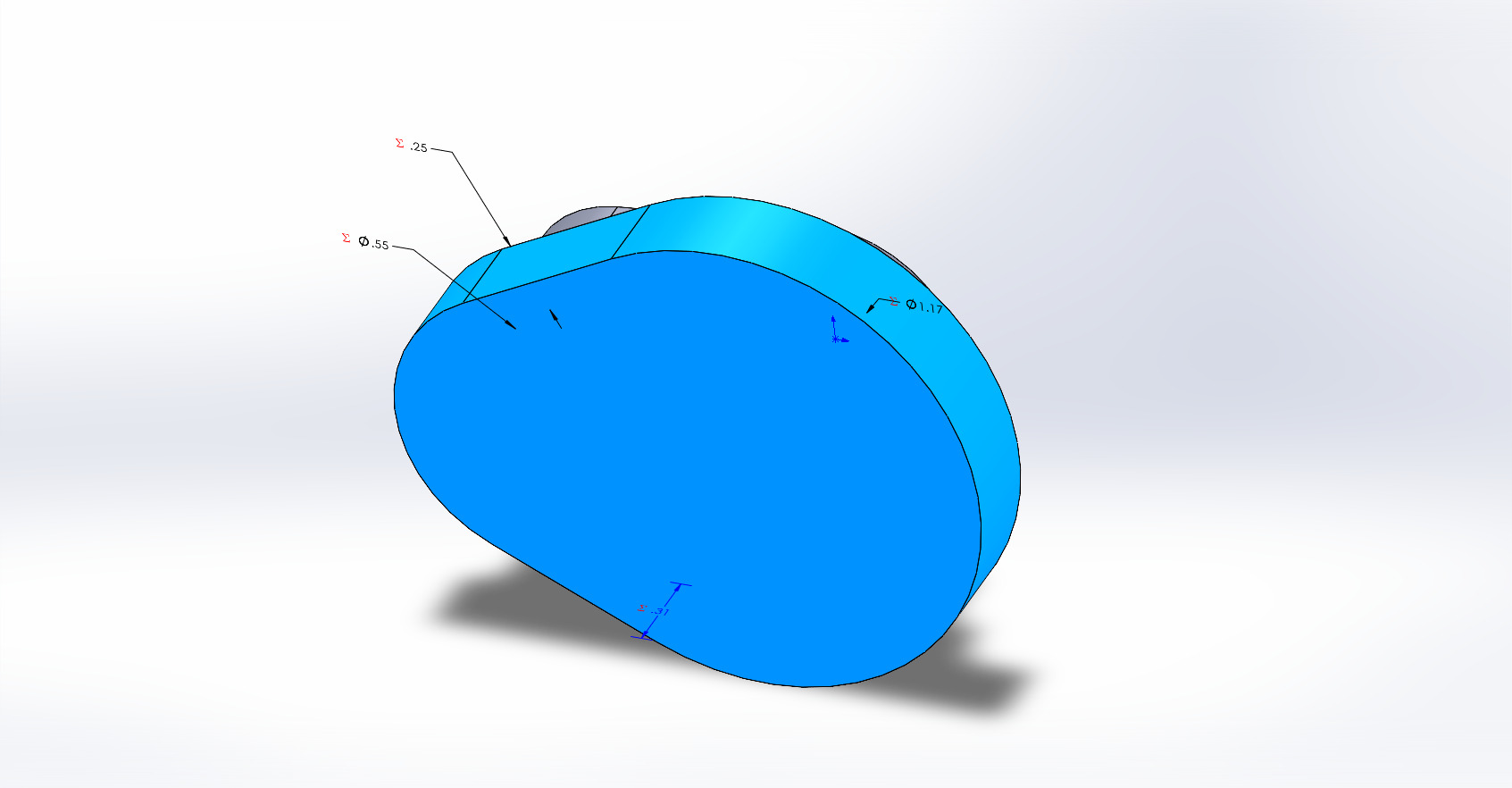
The third extrusion started similarly by keeping my circles concentric to the previous sketches and utilizing the gear diameters instead of the hub diameters. Instead of adding the housing thickness to these dimensions, I instead added the clearance of 1/8" that I wanted around the gears. I then made an offset to that sketch with a distance of the housing thickness and turned the initial sketch into construction geometry so that the part would be solid. It was extruded to a depth of the full gear width - gear hub width + 3/2 clearance. I added the 3/2 of clearance in the part to include a 1/16" clearance between the gears in the housing and the front of the box so that they would stay meshed but free to move without binding on the housing.
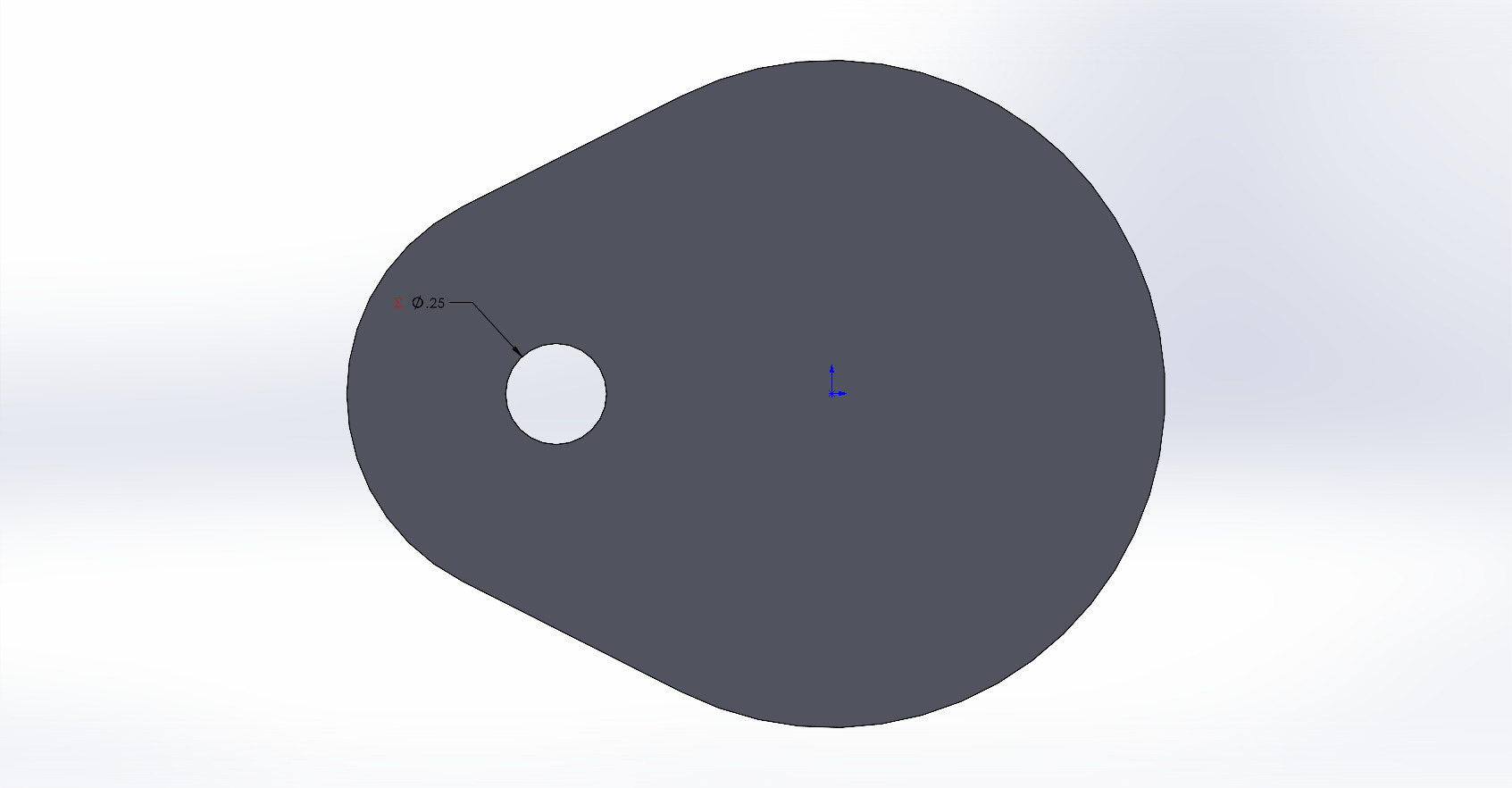
The geometry itself was finished and just needed to be hollowed. I started by adding the input shaft's hole which needed to fit the journal bearing as well. This first cut is a through hole with the diameter of the input shaft's journal bearing.
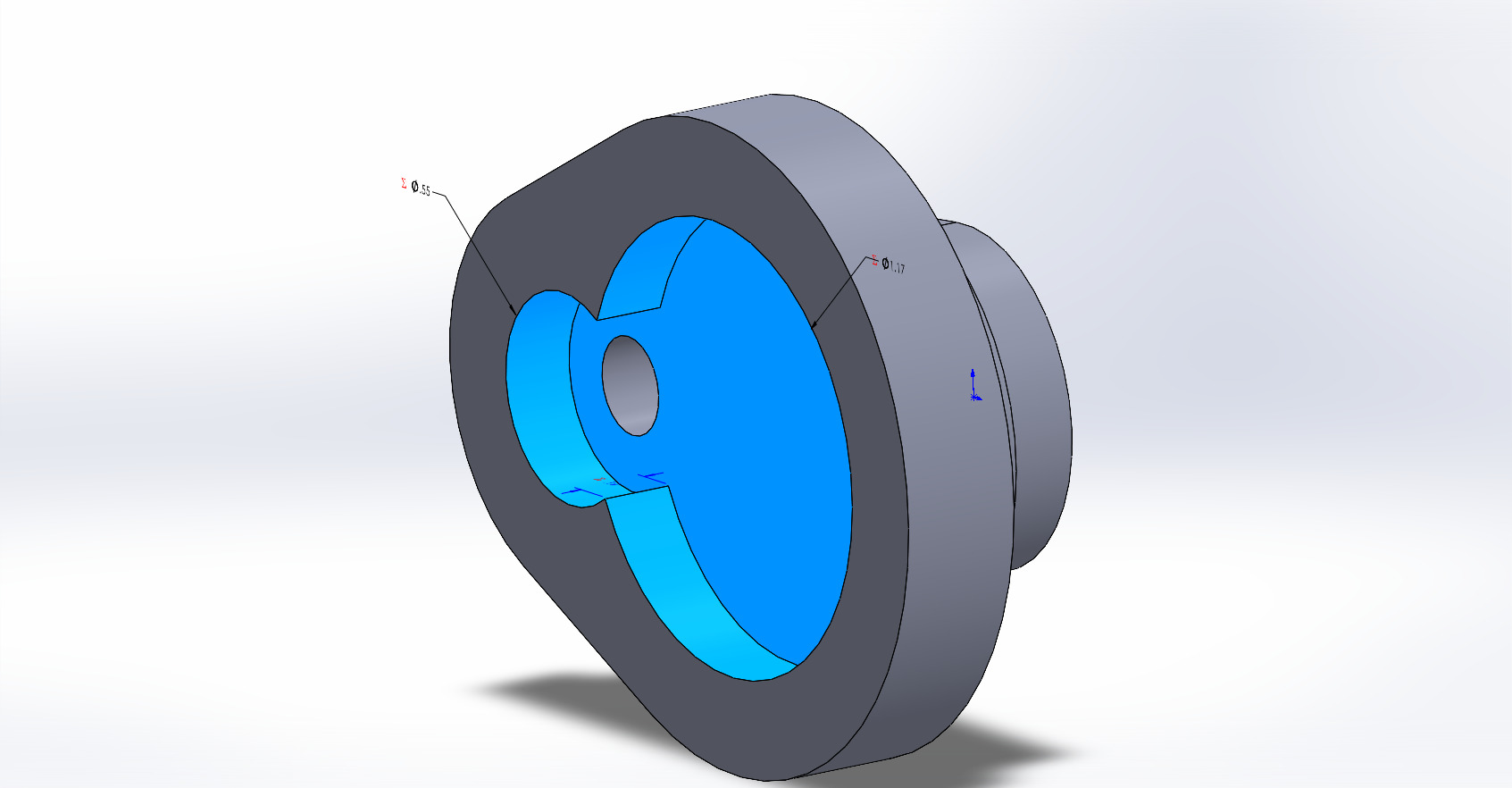
The second cut is the space for the gear teeth to sit. I made the diameters here equal again to the gear diameter plus my clearance, and then extruded the cut to a depth of the full gear width - gear hub width + 1/2 clearance. This half clearance joins with the last extrusion to create a smaller clearance between the two housing faces that will sit on either side of the gear faces. This prevents excess binding/friction as they are free to move back and forth slightly, but not enough to un-mesh the gears.
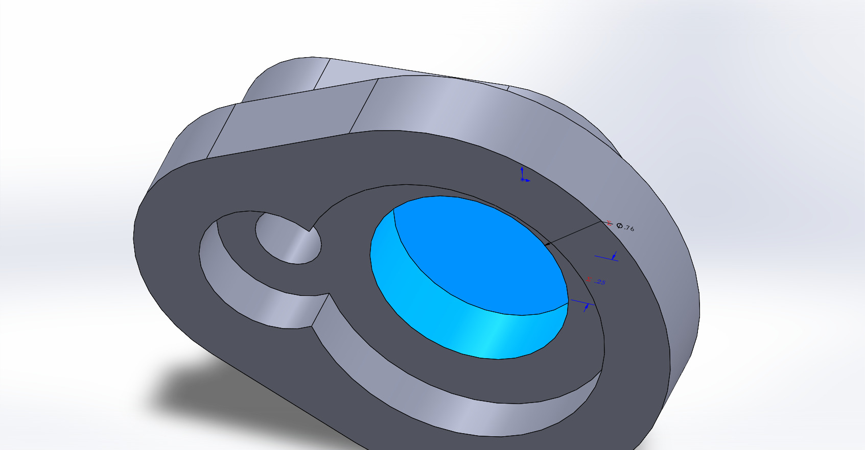
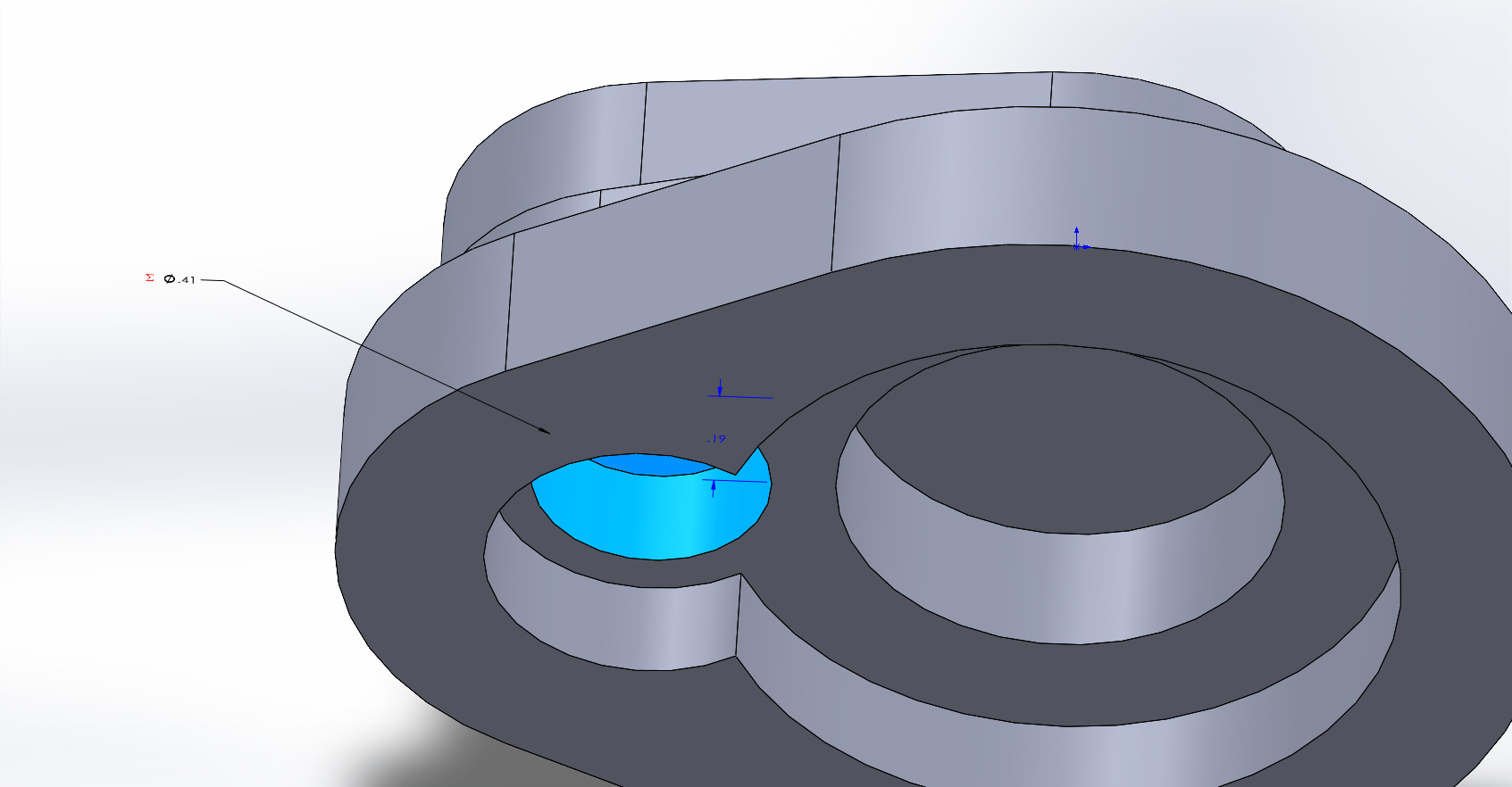
I then added two separate cuts for the depths of the corresponding gear and pinion hub widths.
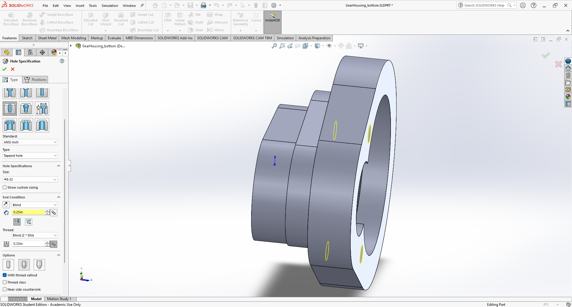
The final feature for the bottom half was the threaded holes to fasten the top half to. This is a major design change from my original sketches, but as I previously explained I found that the bolted connection would be simpler to design than the snap-fit. Since I was under a heavy time-constraint, I decided to add the extra hardware as opposed to designing the snap-fit connection. These two standard holes were placed in locations where there was the most material, and in addition to the output shaft should be more than enough to keep the top half located precisely and secured firmly. This concludes the bottom half of the gearbox housing.
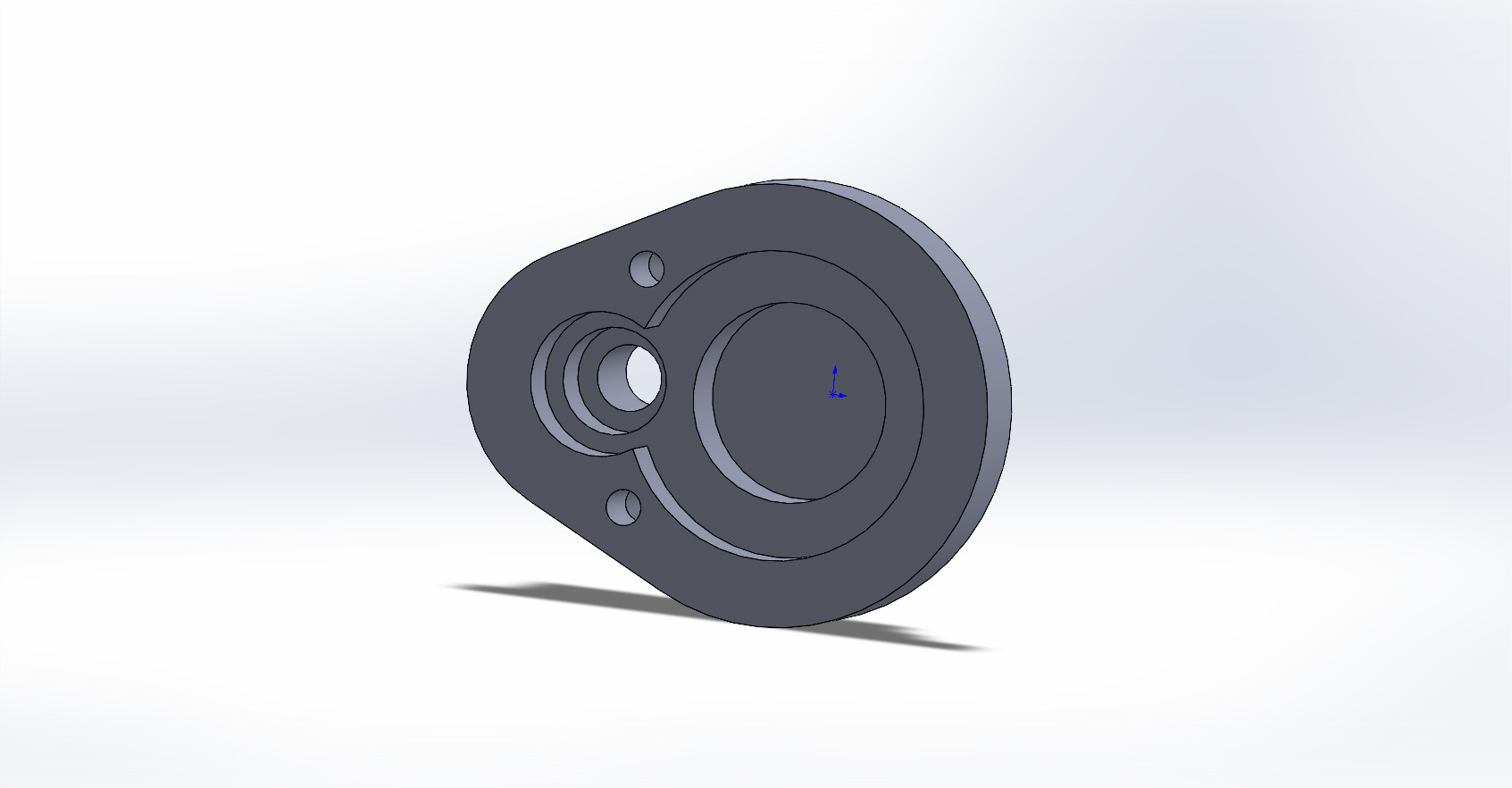
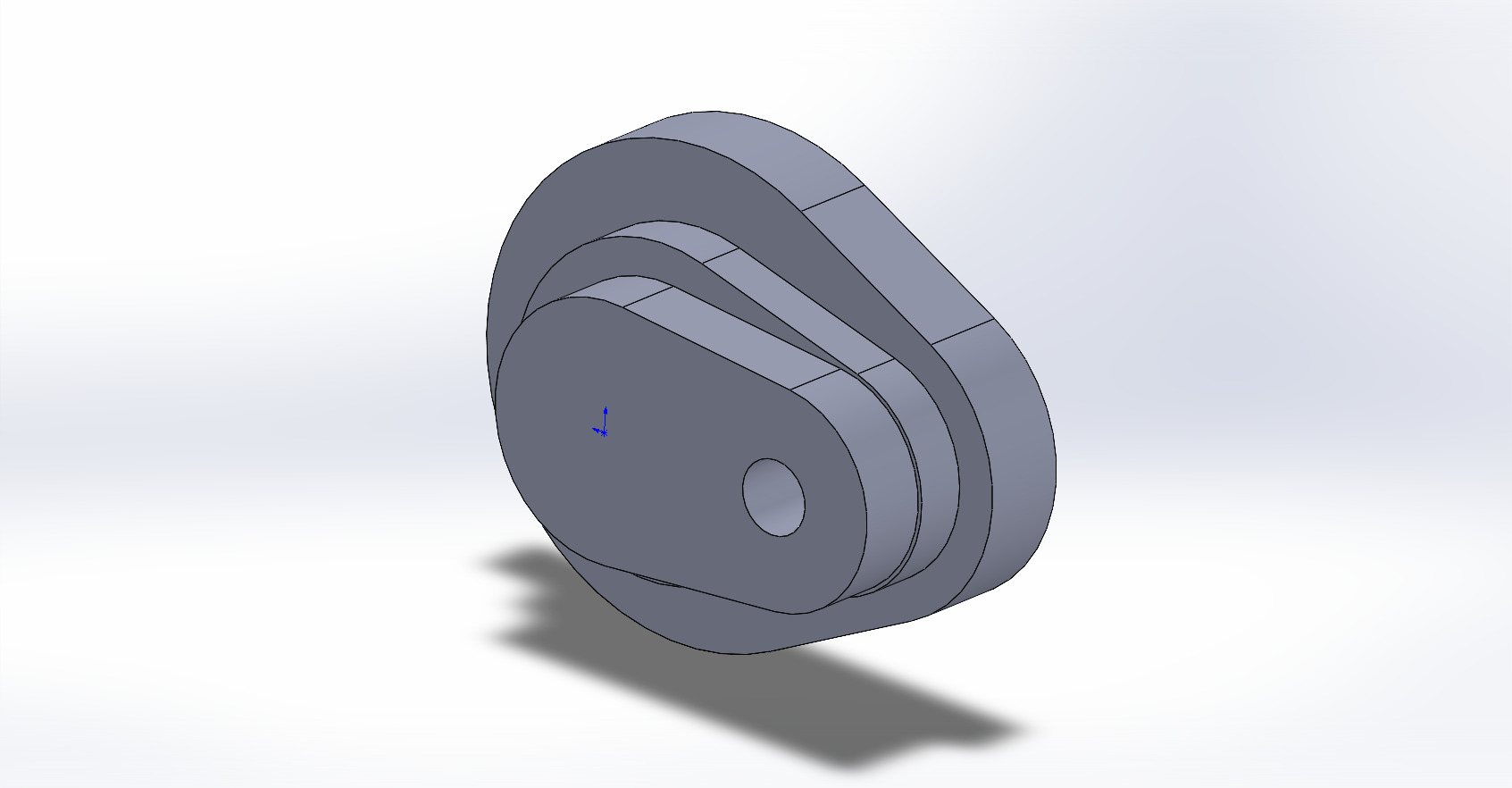
Gear Housing top:
The gear housing top utilizes the same set of global variables as the first model which both point to an external global equations file. This way I would be able to use the same dimensions for the geometry to ensure that the two halves would be sizes accurately.
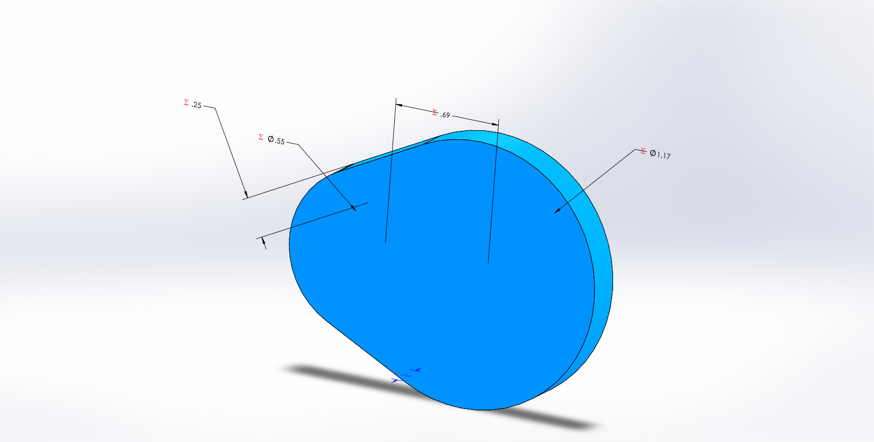
The first sketch was the same as the last extrusion of the gearbox housing bottom half. The depth of the extrusion was set to be the housing thickness.
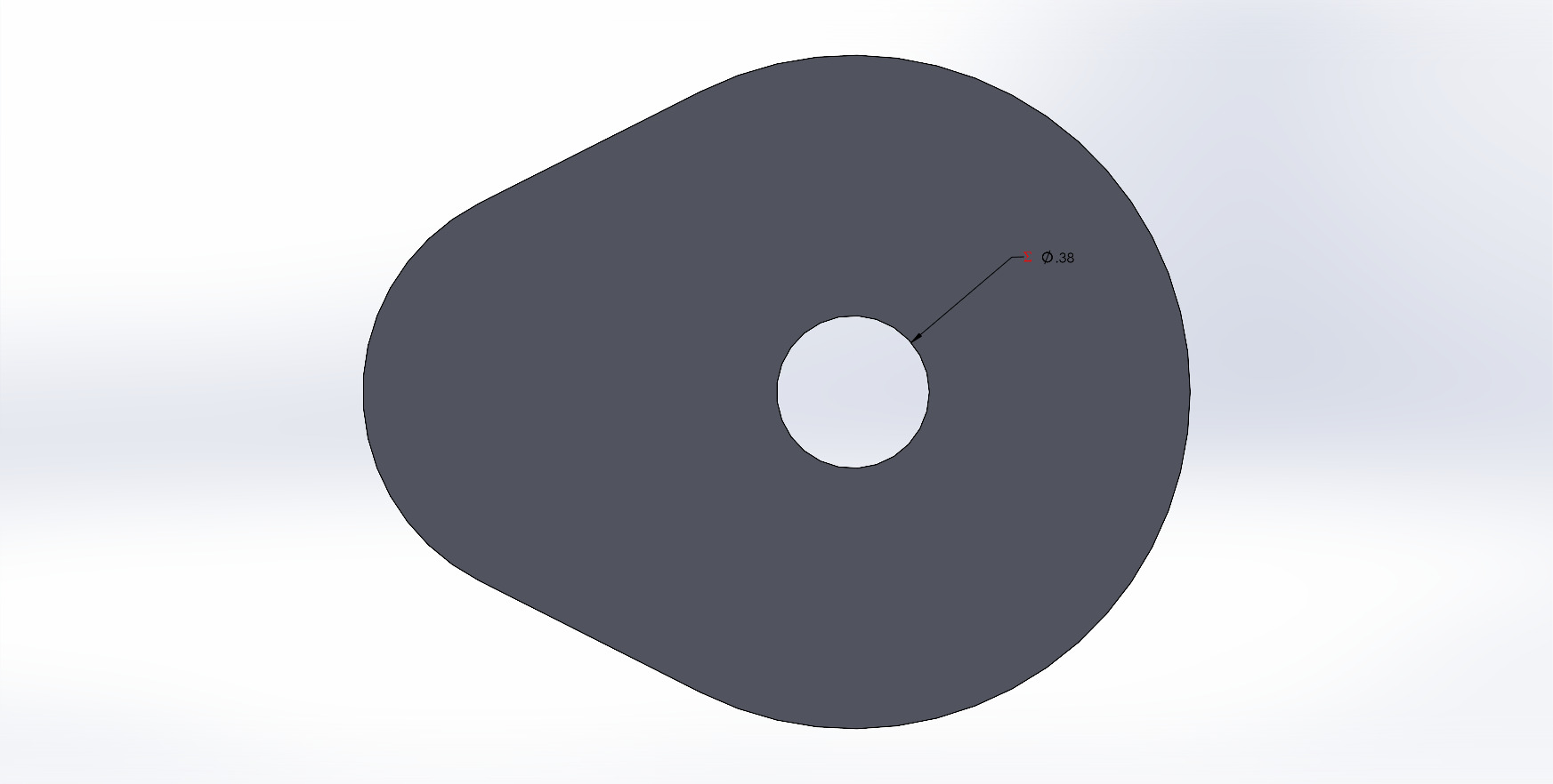
The first cut is to place the output shaft plus its journal bearing. It is a through all cut to a diameter of the journal bearing diameter.
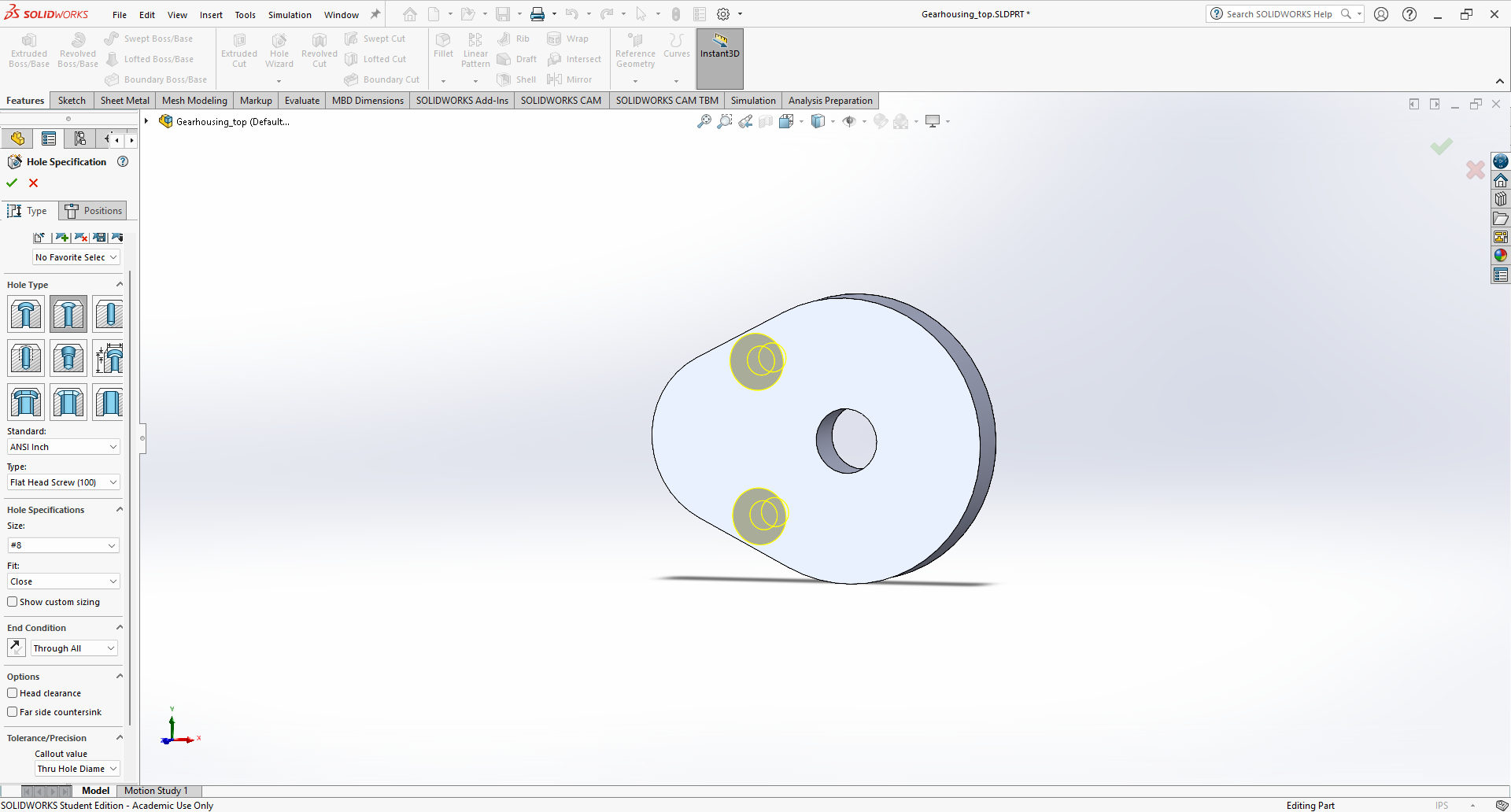
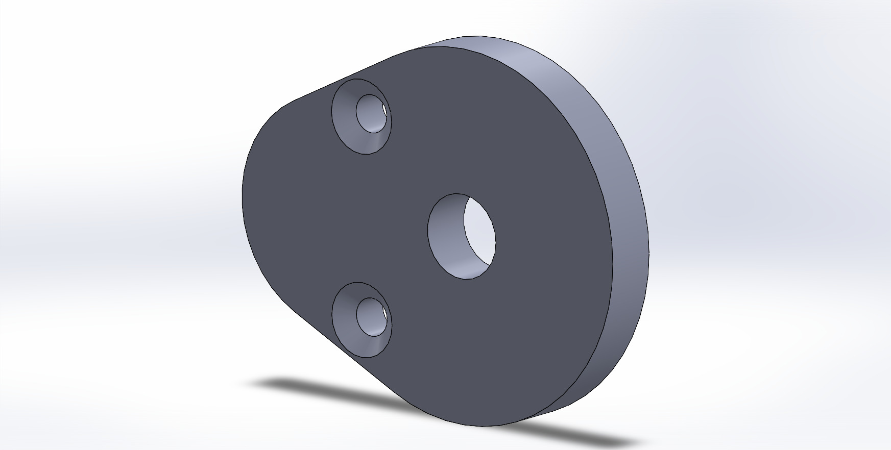
The last feature was the two standard size holes which were countersunk for visual purposes. The use of standard size dimensions for the threads and the clearance holes meant that I could later use a set of SolidWorks included toolkit screws to fasten the two halves together. There will be more information about the screws later in the assembly.
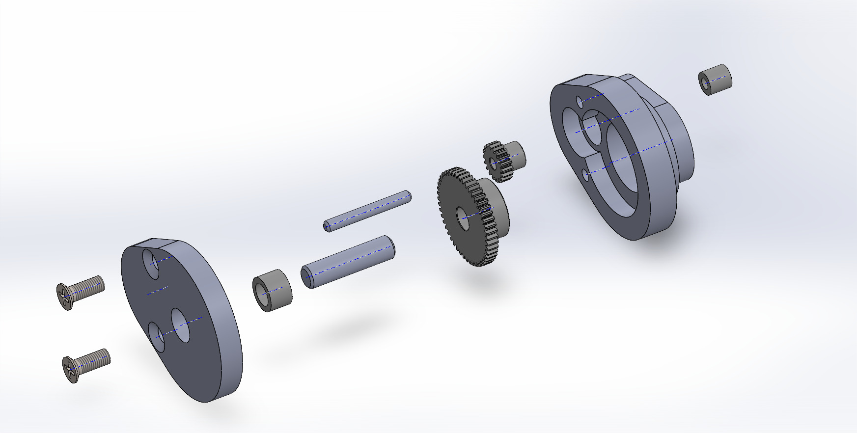
Assembly:
The last thing to do was to put all my parts together to form a final assembly.
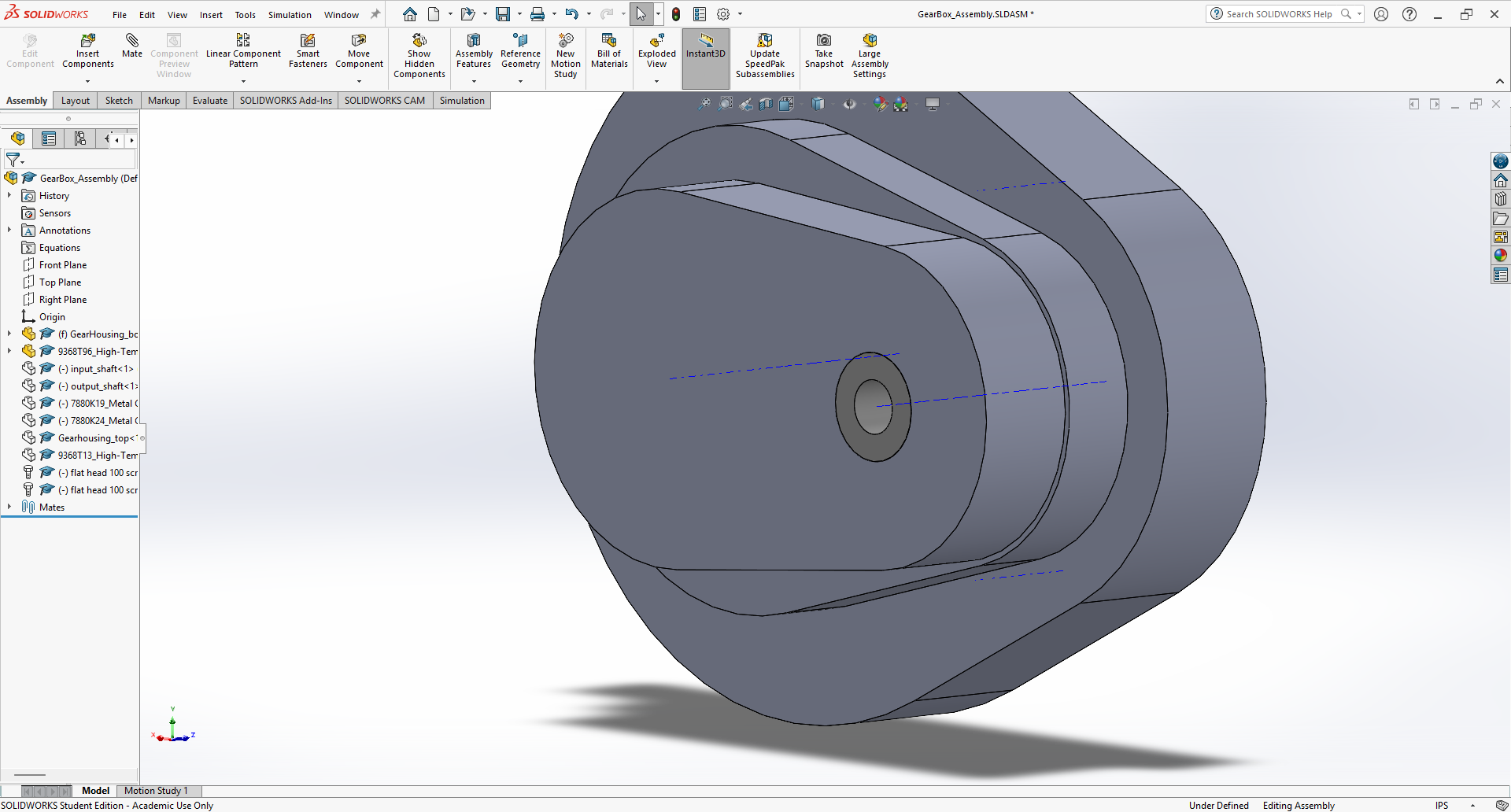
I started by placing the gearbox housing bottom. Followed by the input journal bearing to its correct placement.
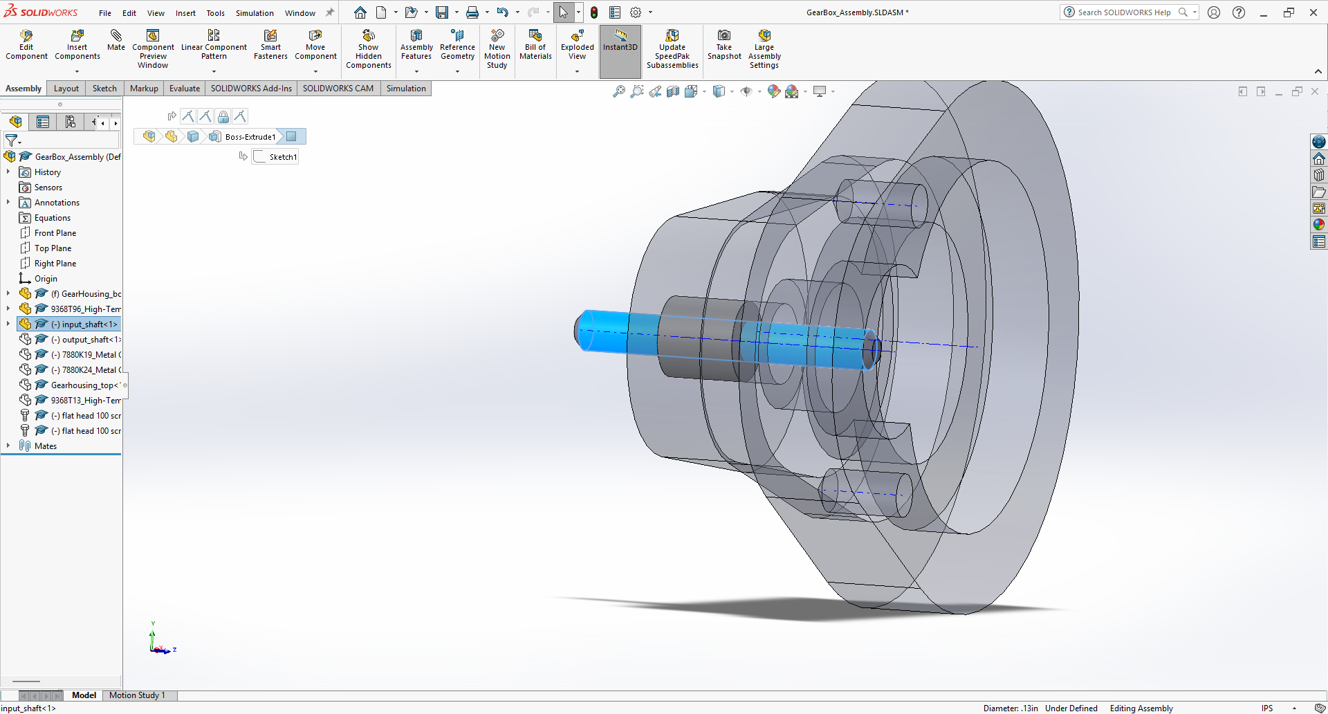
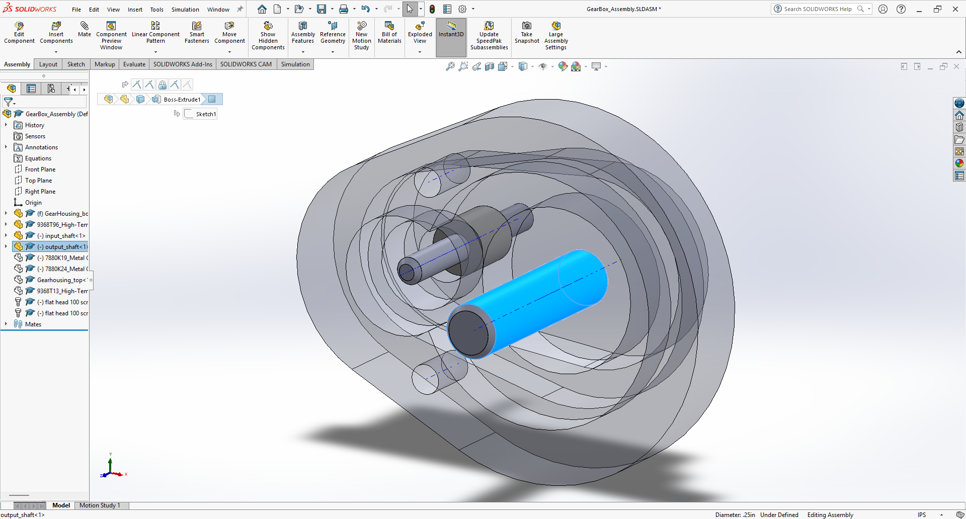
I then placed the input and output shafts on their corresponding axes.
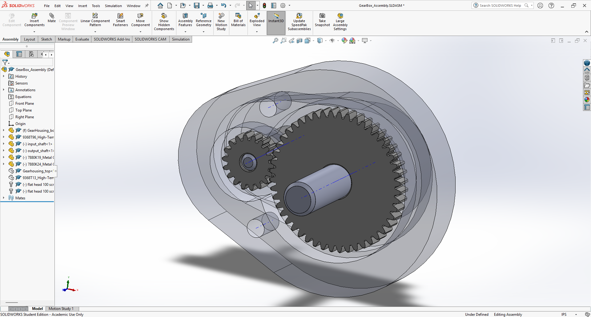
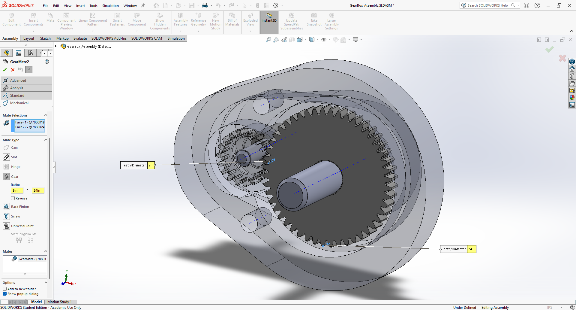
I then placed and mated my gears making sure to give them a gear mate so that they could be rotated realistically in the model.
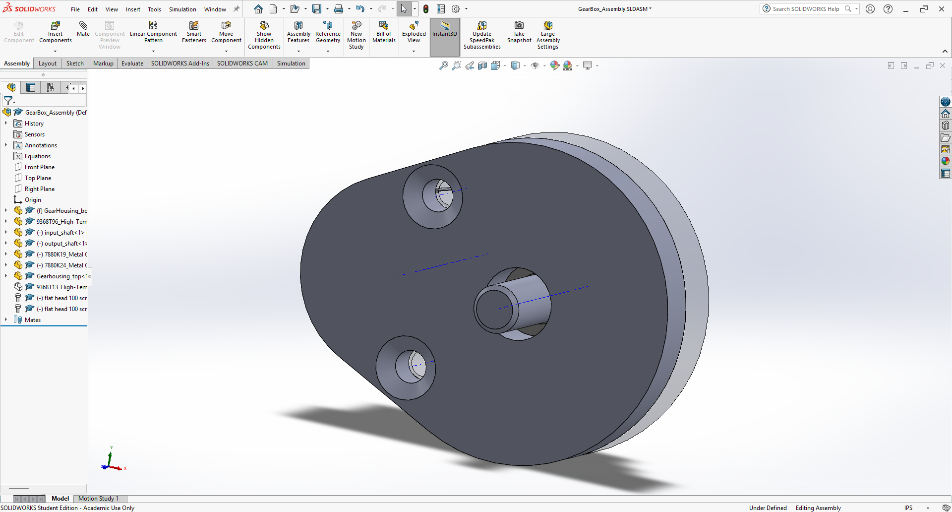
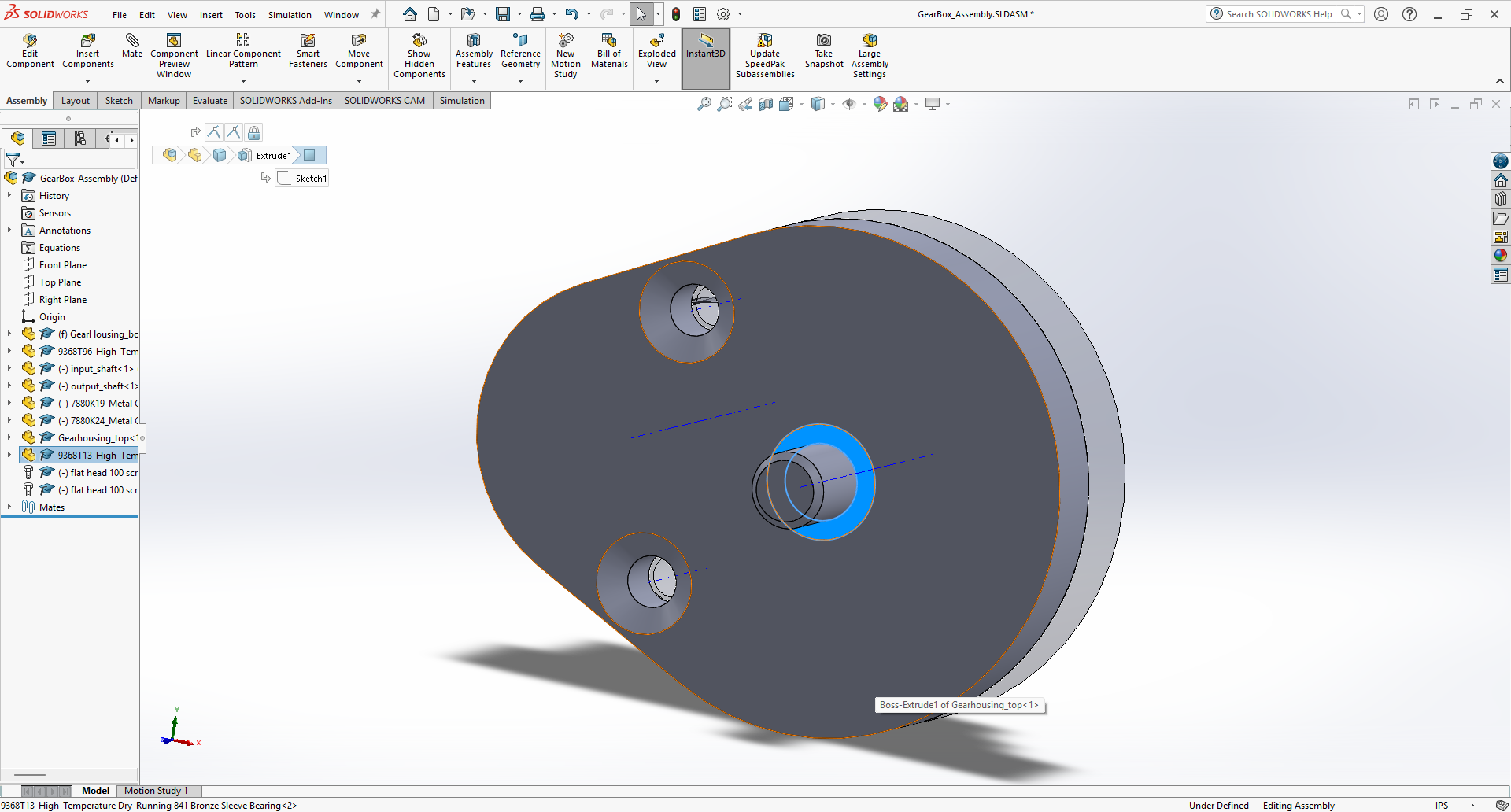
I then added the top of the gear housing followed by the output journal bearing.
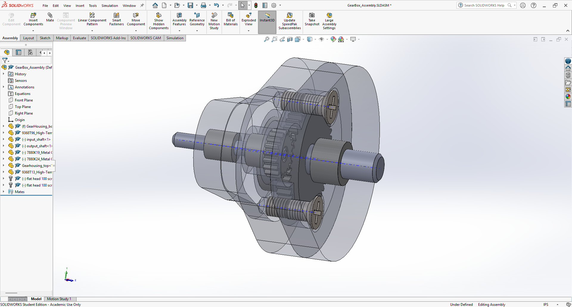
To finish the assembly, I added the two screws that would fasten the housing together. The screws are both ANSI inch 100 countersunk screws, size #8-32, and thread length of 0.4375 inches. These match the threaded holes, clearance holes, and countersinks that I added earlier in the model.
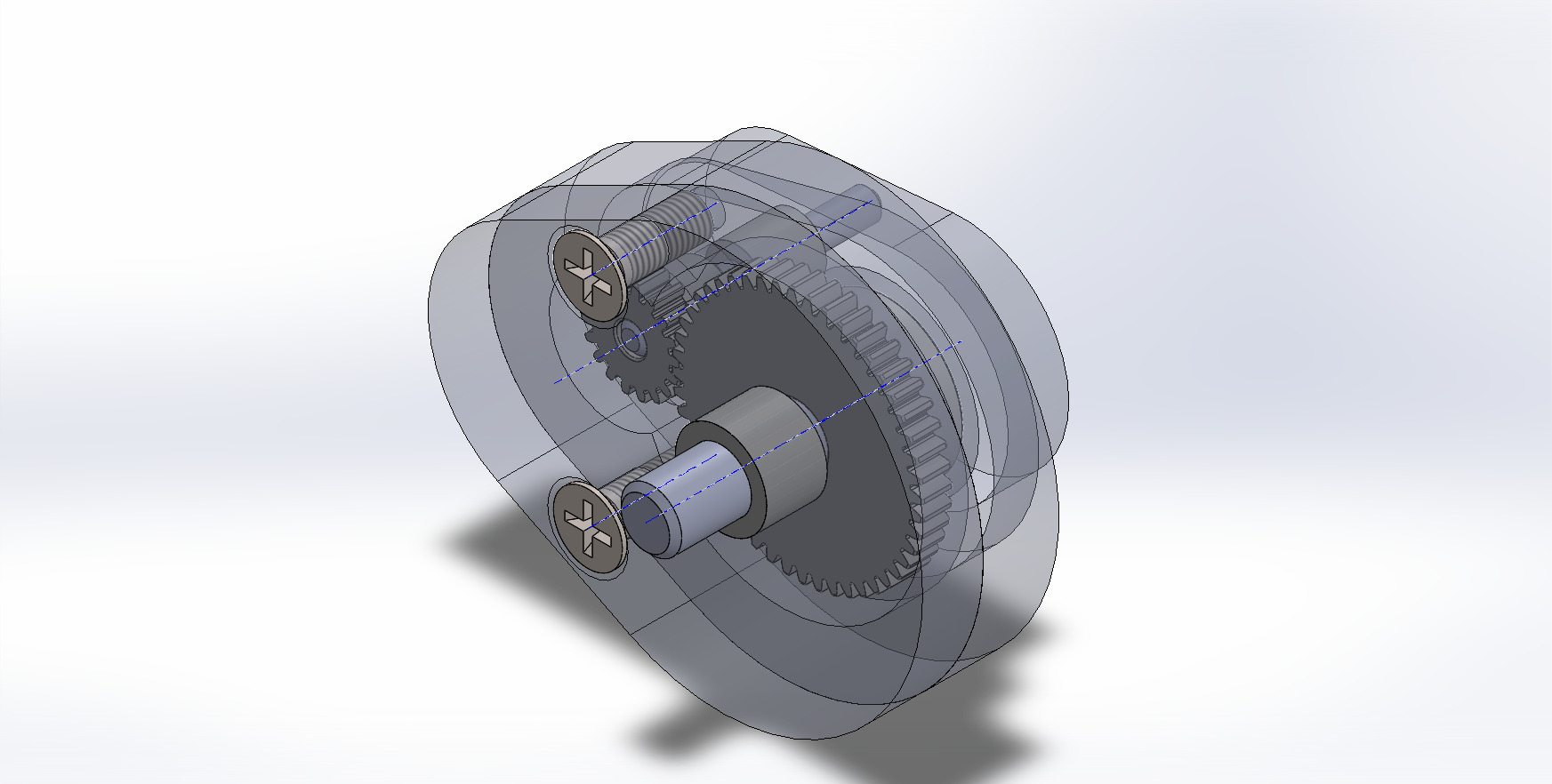
Finished Model Renders:
Lessons Learned
This assignment took me a total of around 10 hours of work for all the necessary calculations, designing, and documentation. The biggest lesson I learned was about shaft and bearing calculations and how to use them within design intent. I also learned the practical skill of how to source real-world components for my design. There were not many new features that I encountered in the CAD software, but the design process was still new to me and taught me the importance of understanding how I want my model to be structured and where important dimensions should be. I'd say that the Design Intent behind the model was a valuable skill developed throughout this assignment, and I think it influenced my decision to include hardware fasteners instead of designing snap-fits for the housing. I thoroughly enjoyed this assignment and think that it taught me a lot about gears, shafts, journal bearings, and design constraints for all of them.