
Bracket Design
This assignment allows students further practice in designing around normal stress, bending stress, and stiffness. This is done through utilization of material properties and designed geometry, while pushing students to utilize their skills learned from classes like statics and solid mechanics. The object being designed for this assignment is a bracket that will slide onto a rigid T beam and support a strap with a symmetrically applied load below.
Objectives:
- Conduct stress analysis to determine appropriate dimensions for structural features.
- Generate free body diagrams (FBDs) to visualize forces and constraints for each feature.
- Identify and document known and unknown variables, assumptions, and algebraic models for stress calculations.
- Perform stiffness analysis to establish minimum required dimensions based on deflection constraints.
- Compare stress and stiffness analyses to ensure structural integrity and compliance with given constraints.
- Create detailed multiview sketches illustrating dimensions derived from both stress and stiffness analyses.
- Reflect on and document key engineering lessons learned throughout the process.
Description:
Detail design a bracket, using the concept design in Appendix B, to hold a horizontal force applied symmetrically by a strap outline in resource #1. The bracket is designed to smoothly slide over the rigid T beam intended for applications where strict accuracy is not crucial. Design using a safety factor of 4 and applied load in between 200 lbf < F < 300 lbf. Choose one of three polymers, HDPE, Torlon® PAI (polyamide-imide), or Nylon. All of the mechanical properties linked in the resource section. Furthermore, state assumptions and approximations about the design in order to use fundamental strength of materials analysis. For example, use the proper stress analysis and deflection analysis where appropriate. Assume no failure due to direct shear stress.
Note: If the bracket is designed symmetrically a lot of work would be cut.
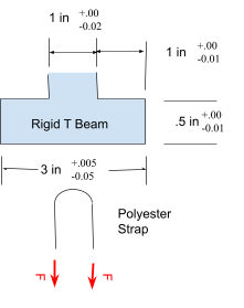
Figure 1.) Specification Visual of the rigid body the bracket affixes to and the polyester strap the bracket needs to hold
*Objectives and Description come from Assignment made by Dr. Fagan
My Process
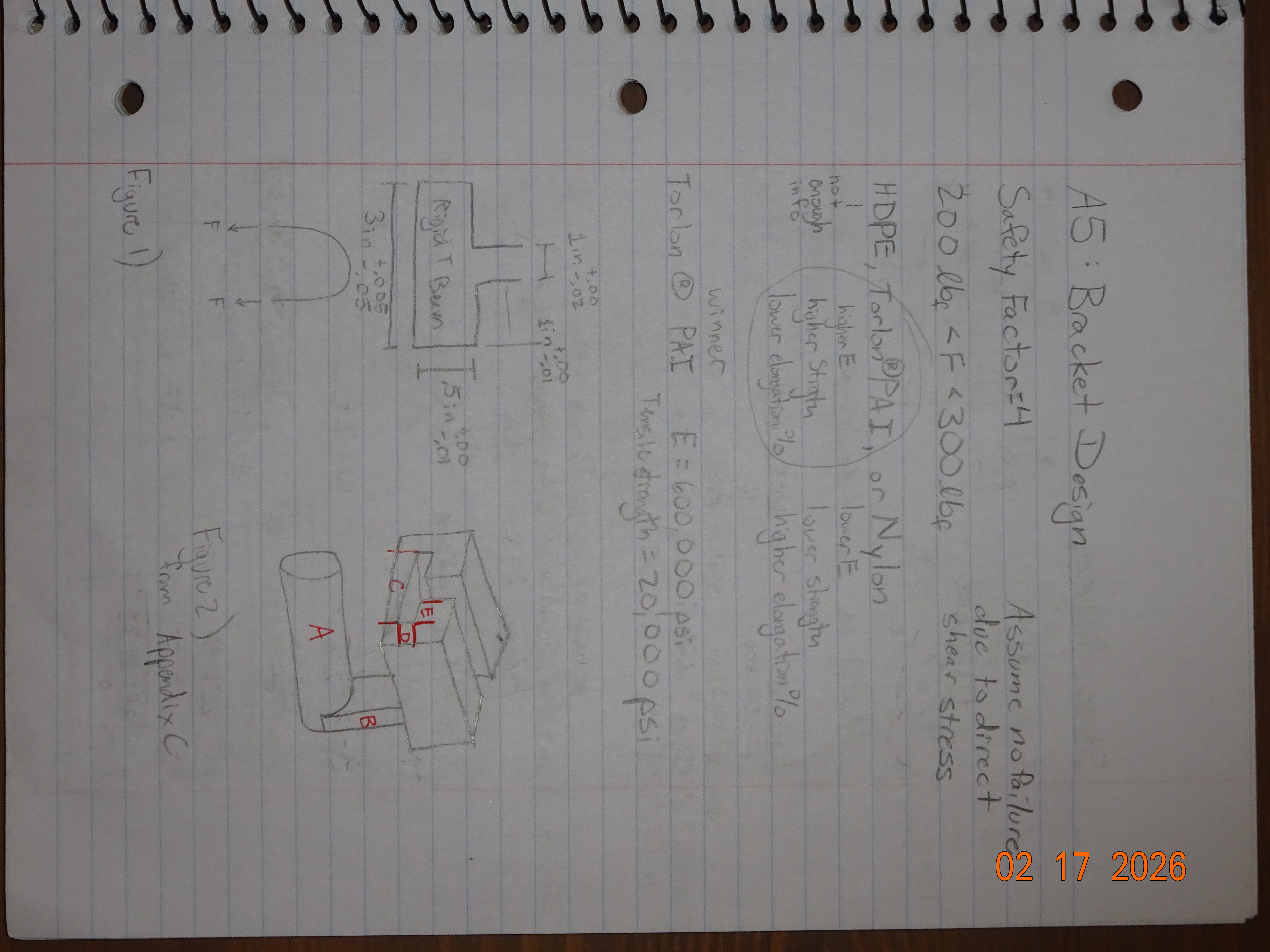
To begin my process, I quickly wrote down all the important information given in the assignment details. This included values like the safety factor, range for the load, assumptions about no shear failure, the figure for the T beam and force, the provided model of the bracket, and my options for material.
Before any calculations could be made, I had to define which material I would be using. A very helpful plastics material table was given through this website by Curbell plastics which made comparisons simple. Of these options, I was able to rule out HDPE fairly quickly since the webpage did not have many material properties listed. Of the other two, Torlon® PAI was the clear choice of polymer due to its high modulus of elasticity, high tensile strength, and low elongation percent. After having the values for modulus of elasticity and tensile strength written down for the material, I was able to begin the analyses of the different sections.
For each analysis, only five sections need to be solved for. This is thanks to a symmetric design which means that the mirrored half will share the same force and resulting dimensions as the other side.
Additionally, for the sake of the provided model, I will be assuming that the length of Sections C-E are equal, that way their cross-sections will all be co-planar with each other for the final bracket. The assignment description also states that the priority is for the bracket to smoothly slide over the T-beam where strict accuracy is not crucial. I took this information to mean that there should be a fair amount of clearance between the bracket and the T-beam. This will be seen throughout my assumptions in the calculations. Both of the final beam calculations leave ample space for the T-beam to slide through but with enough material to securely hold onto the T-beam without slipping or sliding off.
Designing from Stress Analysis
Section A:
Section A was modeled as a cantilever beam with a distributed force. This was suggested through an example problem shown in the assignment description, and I agree that it is a sufficient model for this assignment. The load is equal to two times the given force, since in the provided diagram it shows the force pulling down on each side of where the strap would be.
Known:
- Force = 250 pounds of force (average of the range)
- Tensile yield strength = 20 ksi
- Safety Factor = 4
Unknown:
- Length 'l'
- Diameter 'd'
Assumptions:
- No shear failure
- The length of section A is greater than the width of the strap
- Since the strap is 3/4 inches, we will assume the length of section A is 1 inch
After taking into account the given values and making a few assumptions, the model of Section A can be solved algebraically for the remaining unknown value which in this case is our diameter of the circular cross-section.
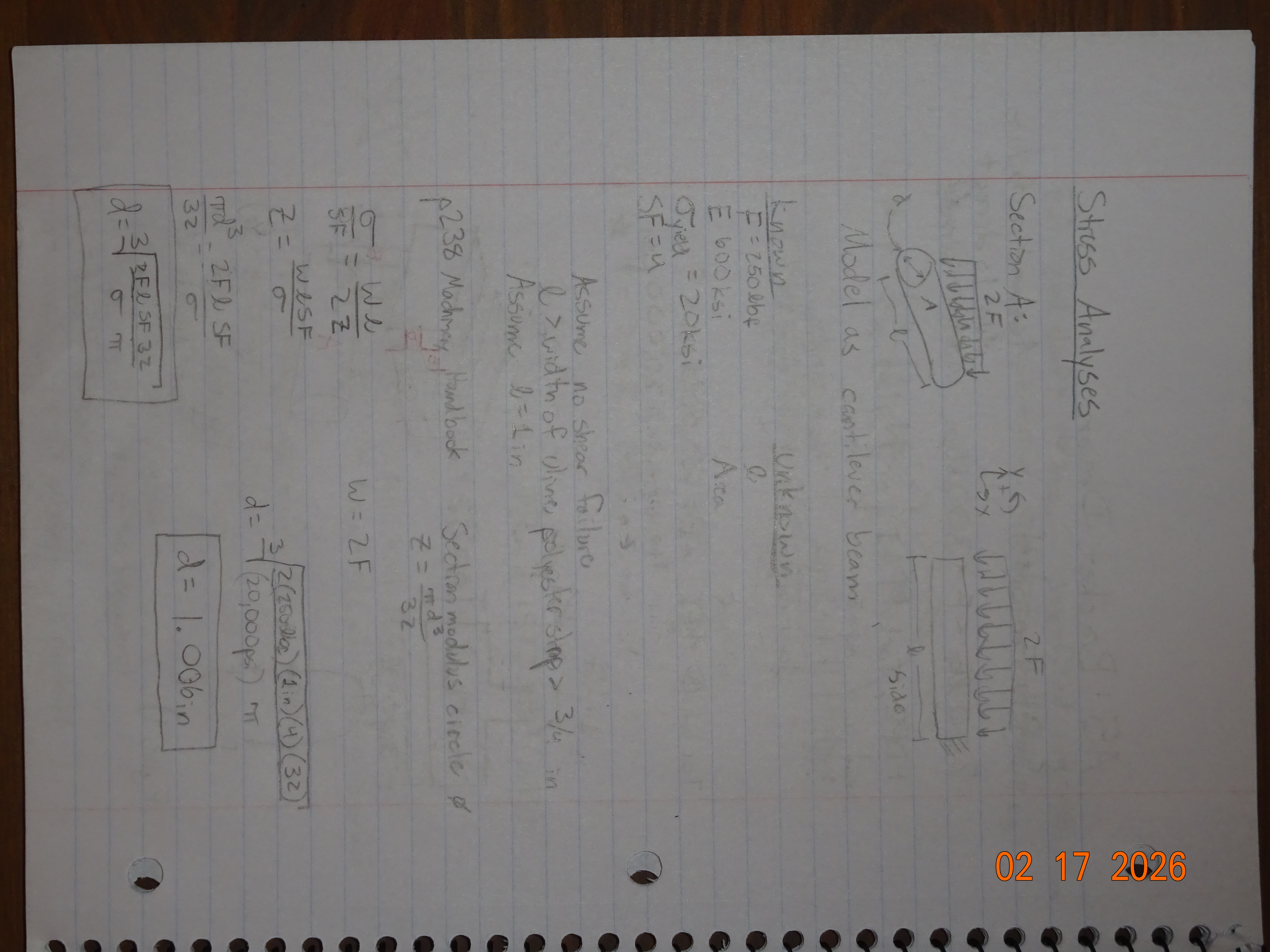
The final dimensions for Stress Analysis: Section A --- diameter = 1.006 inches, length = 1 inch
Section B:
Section B was one of the most challenging sections in my opinion. The difficulty with this section was figuring out how it should best be modeled. I settled on modeling the section as a rod in tension, but this does ignore the fact that the load is really acting as a moment on the beam. This is a large assumption to make in determining the model, but I feel that it is justified thanks to a good safety factor and the fact that it still accounts for the full load on section A as it is concentrated into section B.
Known:
- Force = 250 pounds of force
- Tensile yield strength = 20 ksi
- Safety Factor = 4
Unknown:
- Length 'l'
- Depth 'd'
- Height 'h'
Assumptions:
- No shear failure
- Length = diameter of A = 1.006 inches
- Cross-sectional area = d x l
- Height has to be greater than the diameter of A with clearance to slide strap onto it
- h = 1.25 inches
- Model as a rod in tension
This was the first section that required a second bold assumption for one of its dimensions, the beam in tension does not directly solve for or account for the height of the section B. Because of this, I was at liberty to select a sensible height which I chose as 1.25 to make room for the diameter of section A with some clearance to allow the strap to be slid onto the bracket. With that final assumption, I can continue to solve for the final remaining dimension of depth.
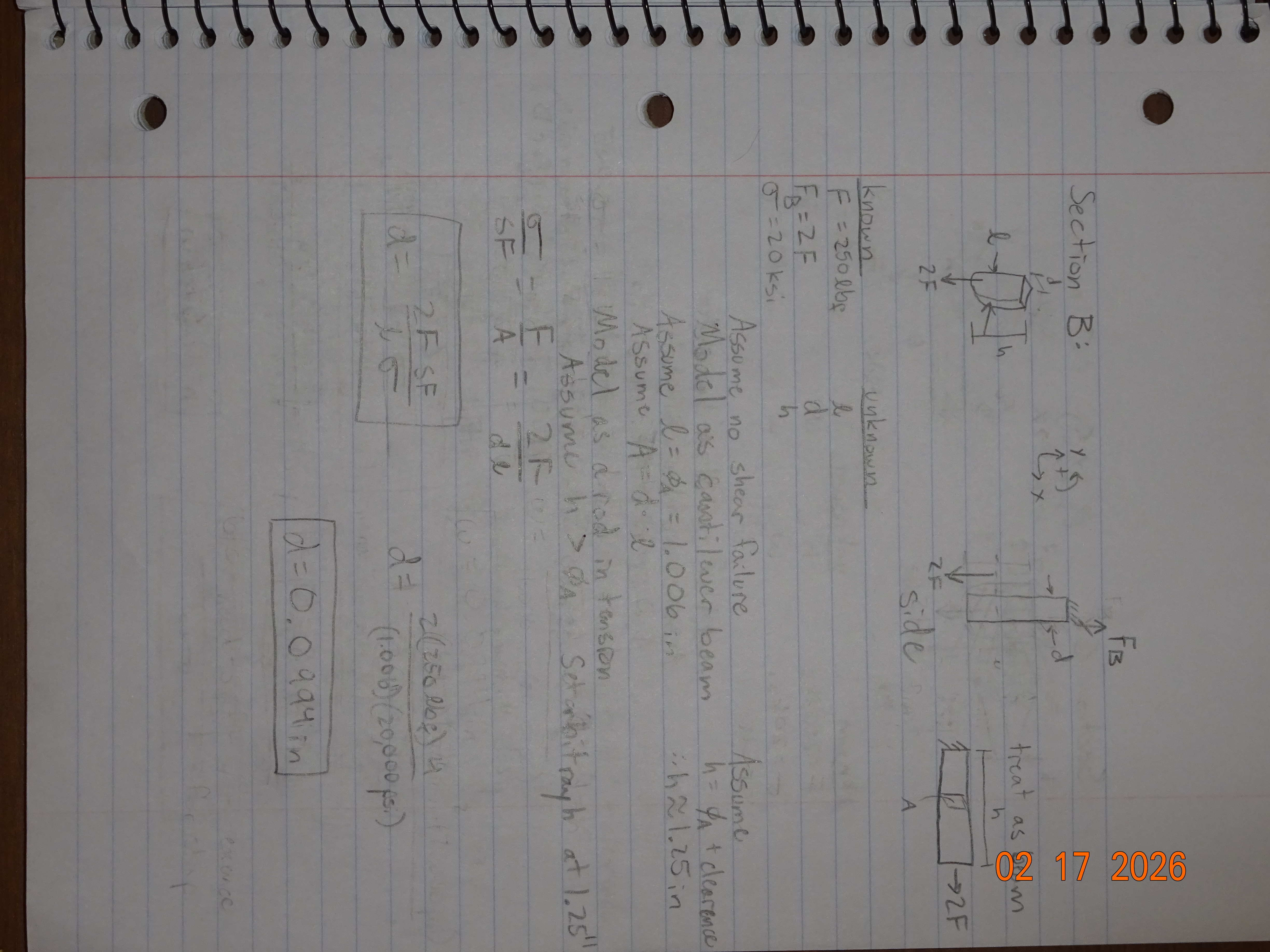
The final dimensions of Stress Analysis: Section B --- height = 1.25 inches, depth = 0.0994 inches, length (better characterized as width) = 1.006 inches
Section C:
Section C was fairly simple and I chose to solve this as a cantilever beam with a point force at its end. I felt this was a suitable model since section C will be supported at one of its top vertices and feel the load on the strap through section B at the opposite side's lower vertex. The force in this case is not distributed, but better described as a point force.
Known:
- Force = 250 pounds of force
- Tensile yield strength = 20 ksi
- Safety Factor = 4
Unknown:
- Height 'h'
- Width 'w'
- Length 'l'
Assumptions:
- No shear failure
- Length = length of section A = 1 inch
- width = width of the T-beam plus space for section D
- width = 3 inches + 2x0.5 inches = 4 inches
The width is only a slight assumption, since it has to be larger than the T-beam's width. The real assumption is that only 0.5 inches will be needed on each side for the width of section D. After the assumptions, the last dimension to be solved for is the height.
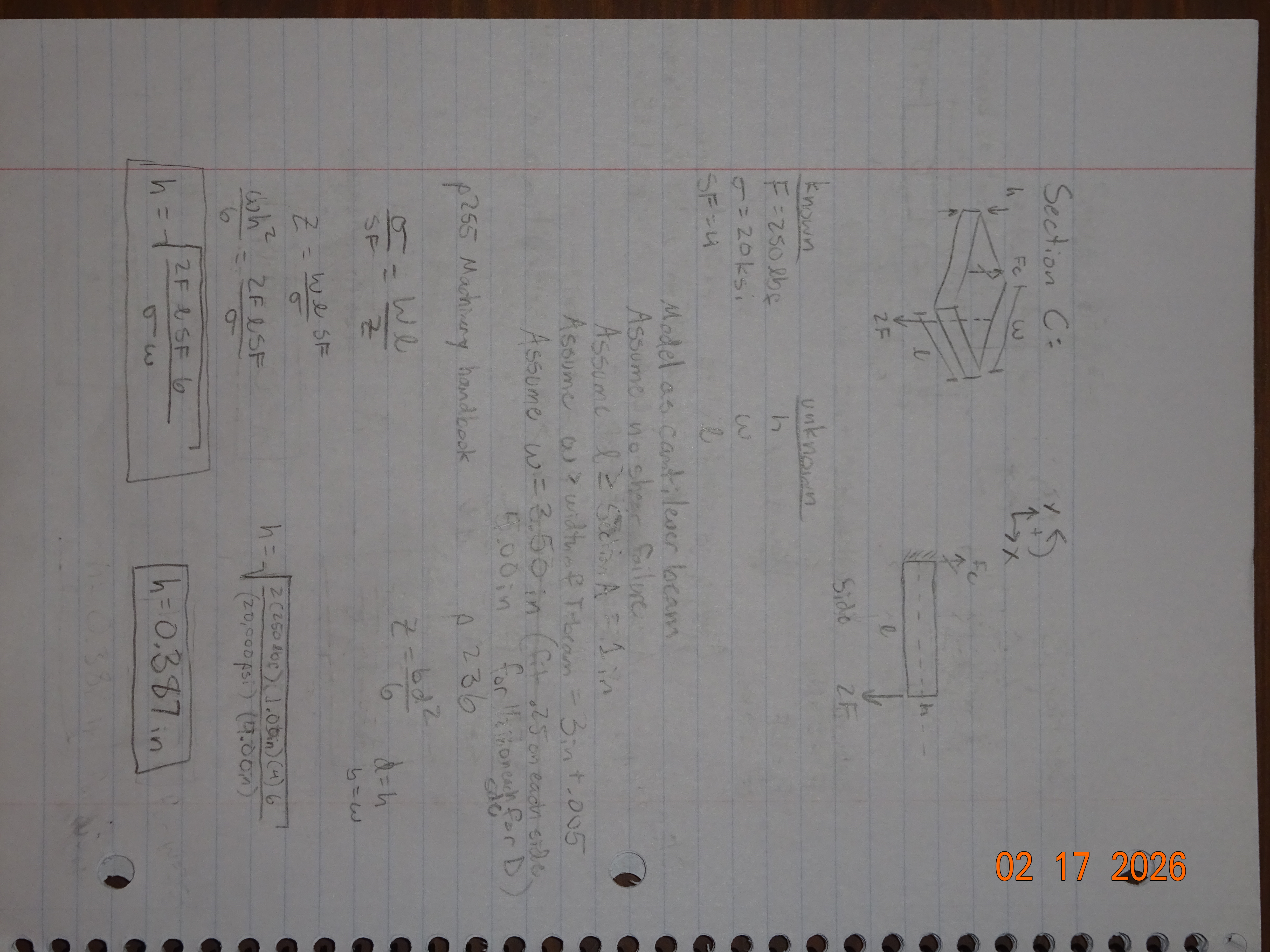
The final dimensions of Stress Analysis: Section C --- width = 4 inches, length = 1 inch, height = 0.387 inches
Section D:
Section D was not very straight forward in its model. I felt that it should be modeled similarly to section C since it will be well supported on the side opposite to the force load through section B, but by this point in the bracket I am assuming the load is felt more as a distributed force over the length of the section.
Known:
- Force = 250 pounds of force
- Tensile yield strength = 20 ksi
- Safety Factor = 4
Unknown:
- Width 'w'
- Length 'l'
- Height 'h'
Assumptions:
- No shear Failure
- Model as a cantilever beam with distributed load
- Length = 1 inch
- Assume height is greater than the flange height of T-beam plus clearance
- h = 0.60 inches
- Target width < 1/2 inch
The width target is set due to the width of C which I set in the previous analysis. If the width was to be determined as larger than half an inch, the T-beam would not have enough space to slot between the two D sections. Fortunately, the calculation for the width was less than half an inch with about 0.1 inches to spare. This leaves space for the T-beam to easily slide into the bracket.
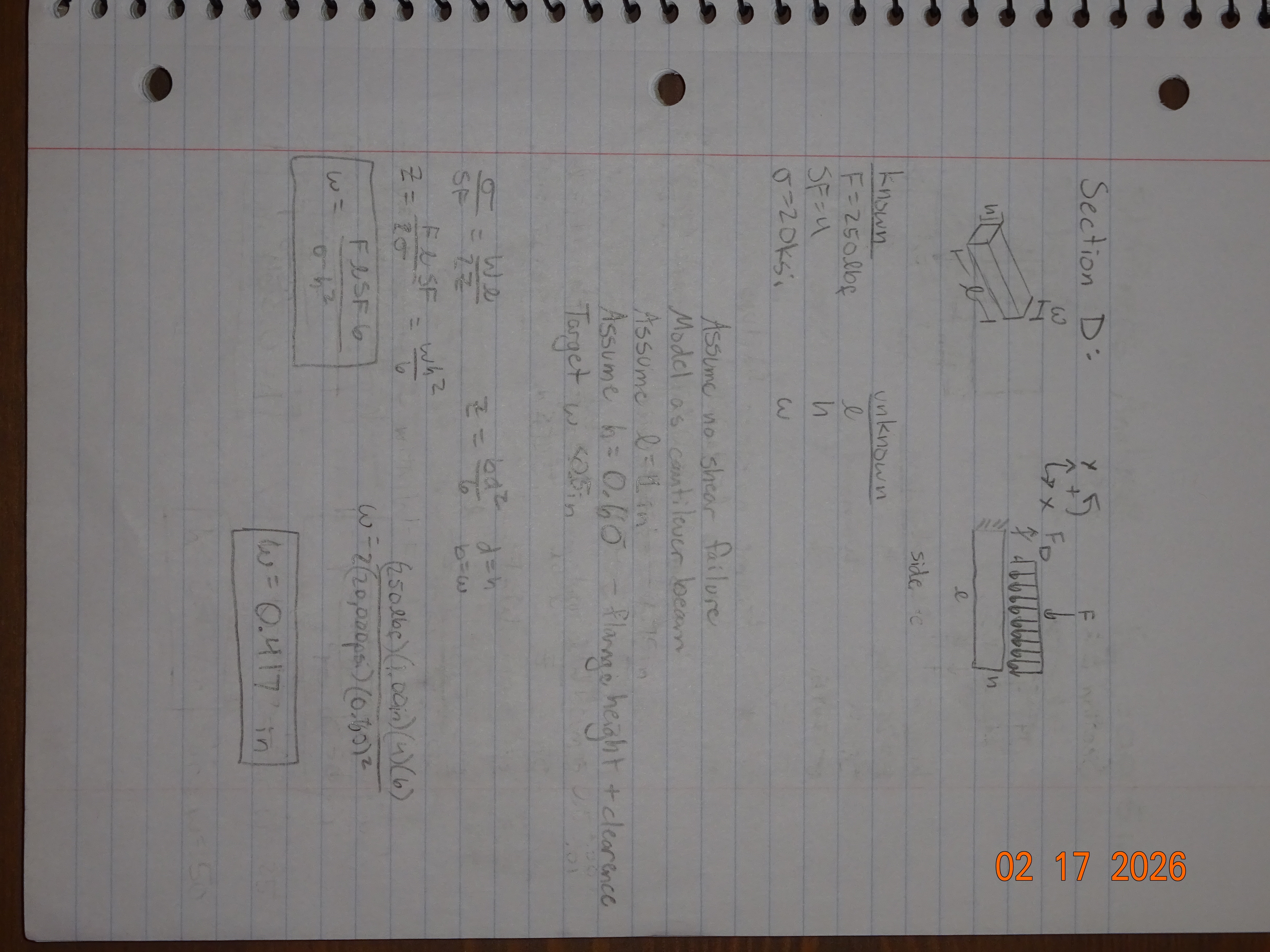
The final dimensions of Stress Analysis: Section D --- height = 0.60 inches, length = 1 inch, width = 0.417 inches
Section E:
Section E will rest on top of the flanges on the T-beam, and so it is best modeled as a cantilever beam where the material on top of the flange is ignored. Since section D was modeled as a distributed load, it seems fair to represent the force in section E as a point force on the outside length of the section. The width of the T-beam flange is 1 inch on each side, so to get my final width dimension, I add 1 inch to the value for section D's width. Section D's width is also equal to the overhang length of Section E.
Known:
- Force = 250 pounds of force
- Tensile yield strength = 20 ksi
- Safety Factor = 4
Unknown:
- Height 'h'
- length 'l'
- width 'w'
Assumptions:
- No shear failure
- Length = 1 inch
- Overhang width = 0.417 inches
With those assumptions, only one variable was left for the height of section E. This is the final dimension needed for the bracket in the stress analysis.
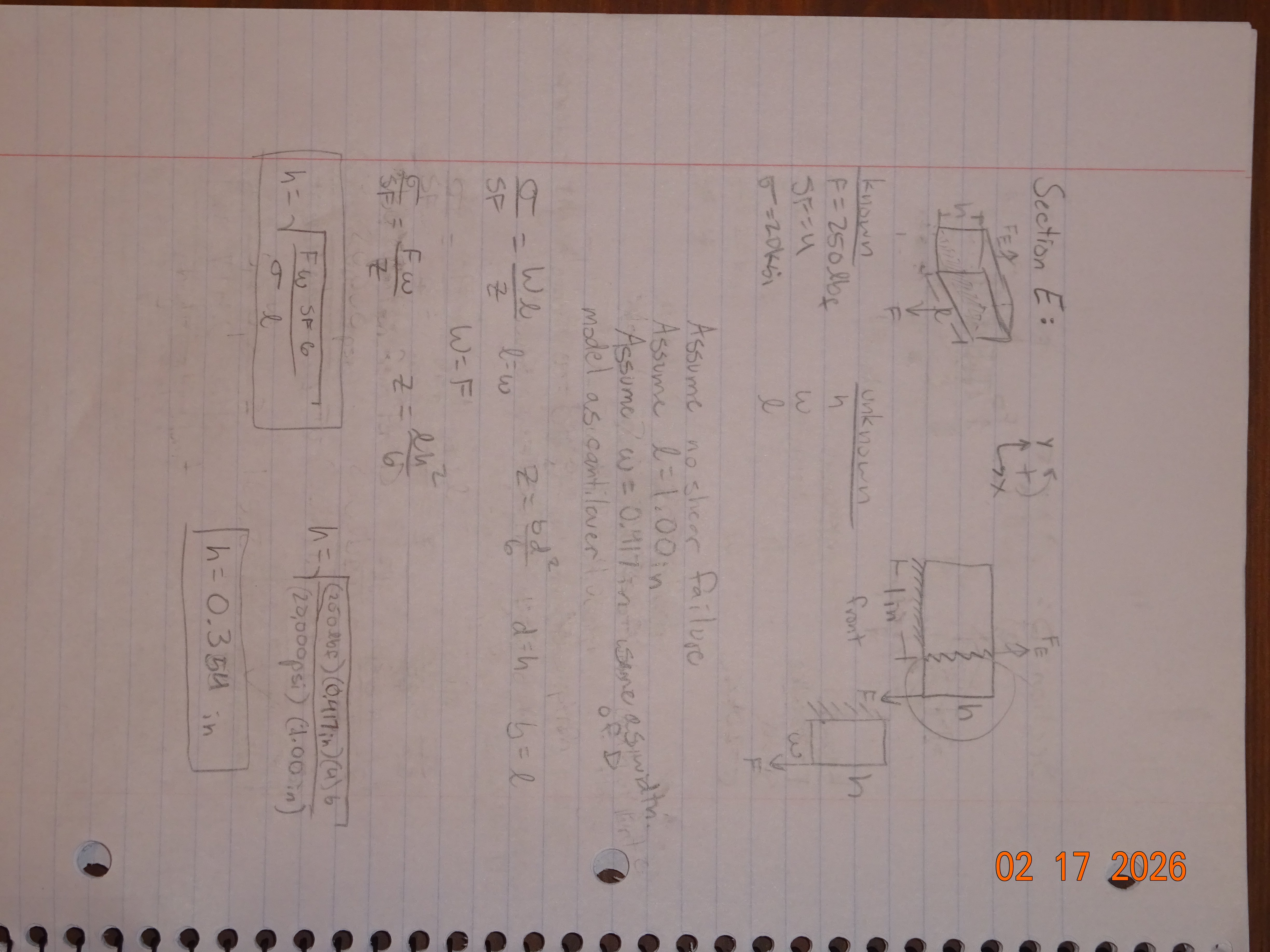
The final dimensions of Stress Analysis: Section E --- length = 1 inch, width = 1.417 inches, height = 0.354 inches
Designing from Stiffness Analysis
Section A:
For the stiffness calculations, I left most of the models the same as when I solved for the stress analysis. This made the calculations a little more straight forward, since I only had to find the correct equation for deflection of the model I used previously.
Known:
- Force = 250 pounds of force
- Modulus of Elasticity = 600 ksi
- max deflection = 0.005 inches
- Safety Factor = 4
Unknown:
- Length 'l'
- Diameter 'd'
Assumptions:
- Shear deflection negligible
- Length = 1 inch
The cantilever beam model has a straight forward equation, and so the diameter is solved for. From this value, I am able to see that the deflection will be much more of a limited factor for the bracket dimensions since the calculated value for the deflection analysis was half an inch larger than for the stress analysis. This trend will continue for most of the remaining sections.
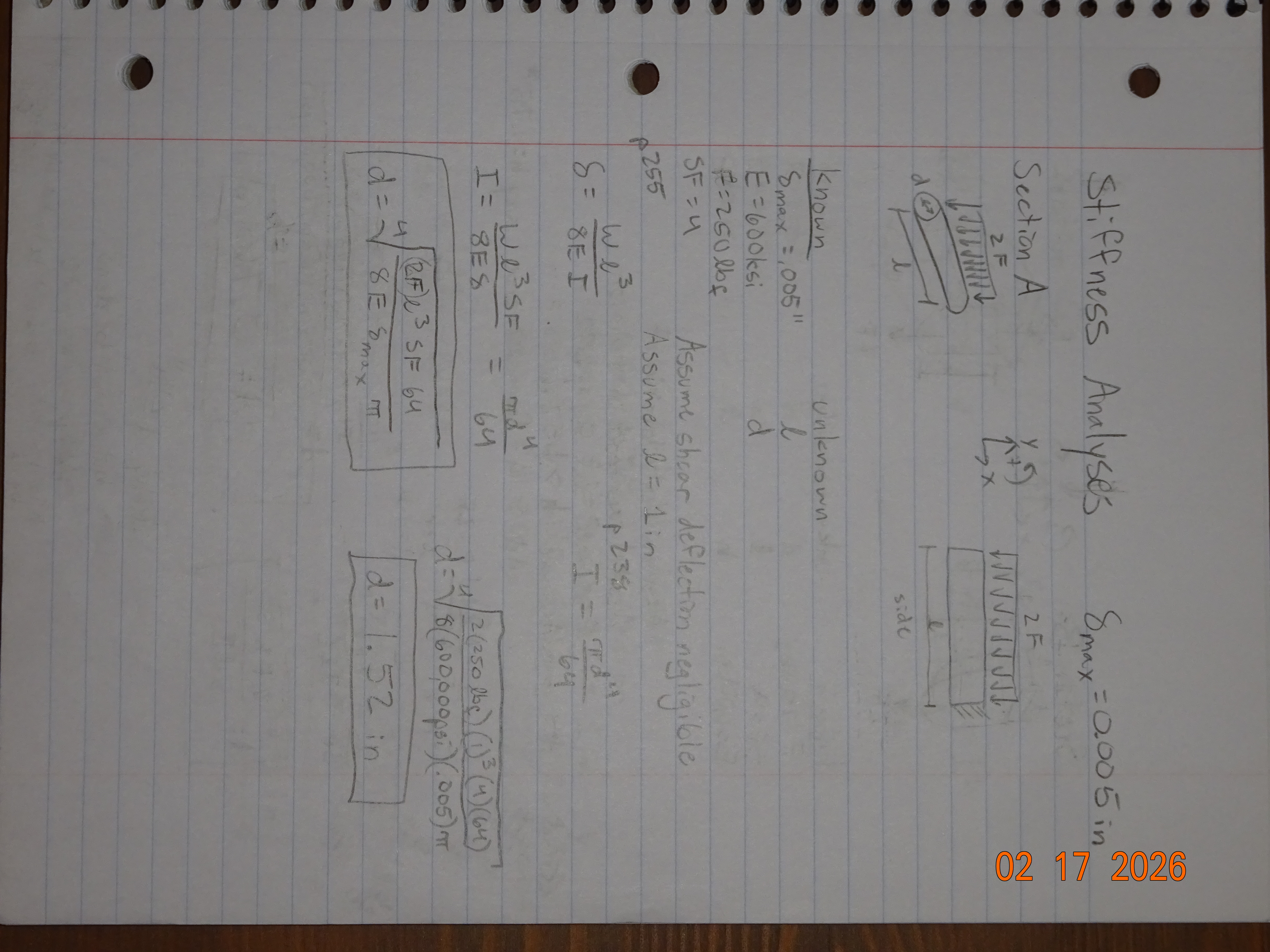
The final dimensions for Stiffness Analysis: Section A --- length = 1 inch, diameter = 1.52 inches
Section B:
Section B was again the most challenging section. The model I chose earlier was already less accurate than I had hoped, but worked as a simple model for the forces on the section. The difference for the stiffness analysis is that the deflection is being applied to the cross-sectional area of section B and thus generates a much larger diameter. This could have been avoided by setting my depth value and solving for the height, but I felt that this would result in either a height value that was too small or far too large for the bracket design. This meant that I would have to make do with the depth calculated depth value.
Known:
- Force = 250 pounds of force
- Modulus of Elasticity = 600 ksi
- max deflection = 0.005 inches
- Safety Factor = 4
Unknown:
- Depth 'd'
- Length 'l'
- Height 'h'
Assumptions:
- Shear deflection negligible
- Model as rod in tension
- Length = diameter of A = 1.52 inches
- Height > diameter of A + clearance for strap (~.25 inches) = 1.75 inches
With these assumptions, the last dimension remaining is the depth, which again was much larger than the stress analysis depth.
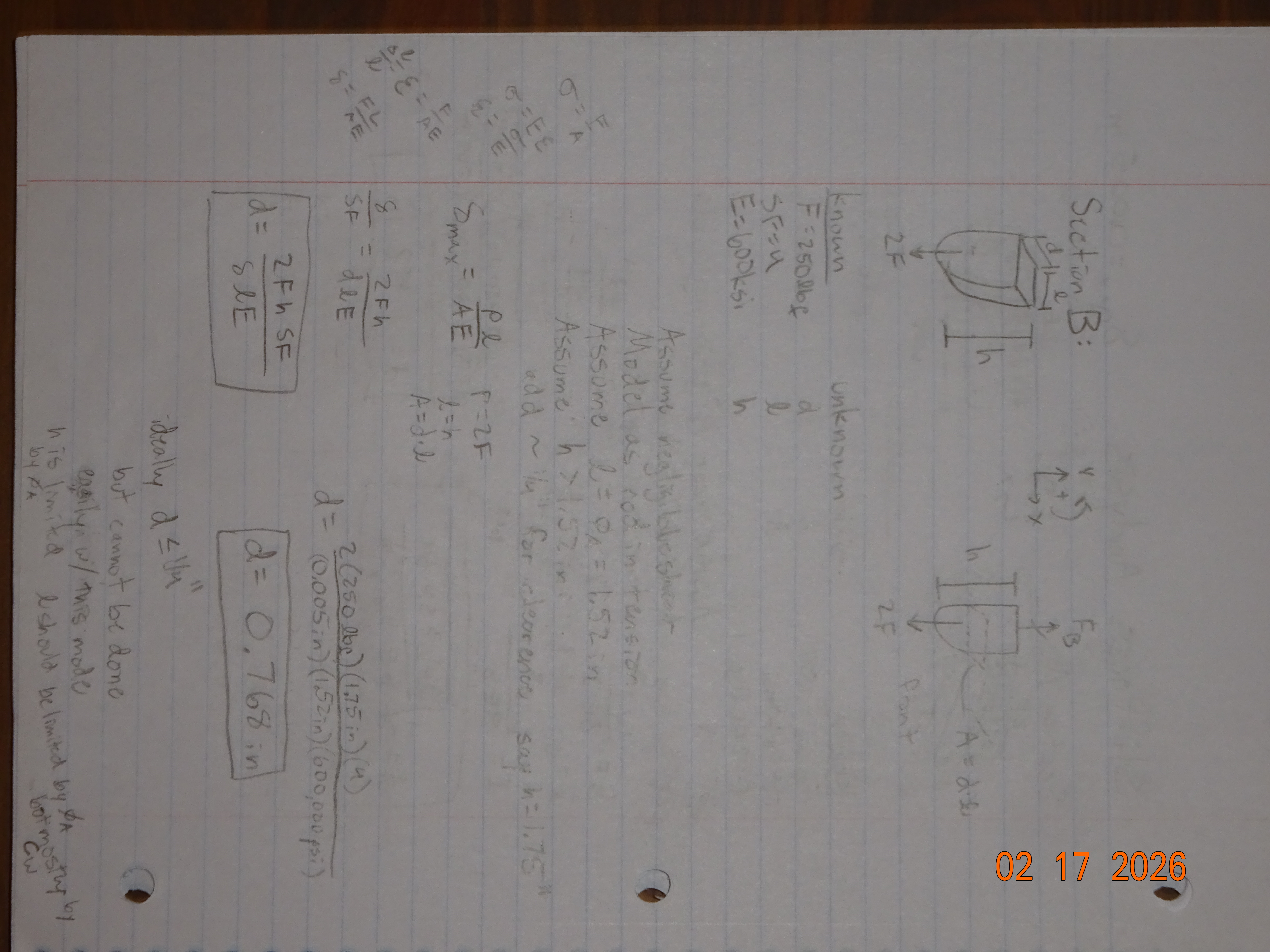
The final dimensions of Stiffness Analysis: Section B --- height = 1.75 inches, length (better described as width) = 1.52 inches, depth = 0.768 inches
Section C:
Section C is fairly straight forward just like the stress analysis. The cantilever beam model means readily available equations for max deflection.
Known:
- Force = 250 pounds of force
- Modulus of Elasticity = 600 ksi
- max deflection = 0.005 inches
- Safety Factor = 4
Unknown:
- Height 'h'
- Width 'w'
- Length 'l'
Assumptions:
- Shear deflection is negligible
- Length >= section A length = 1 inch
- Width > width of T-beam + 1/2 inch for section D on each side
- w = 4.00 inches
The height is again the only remaining dimension and is easily solved for.
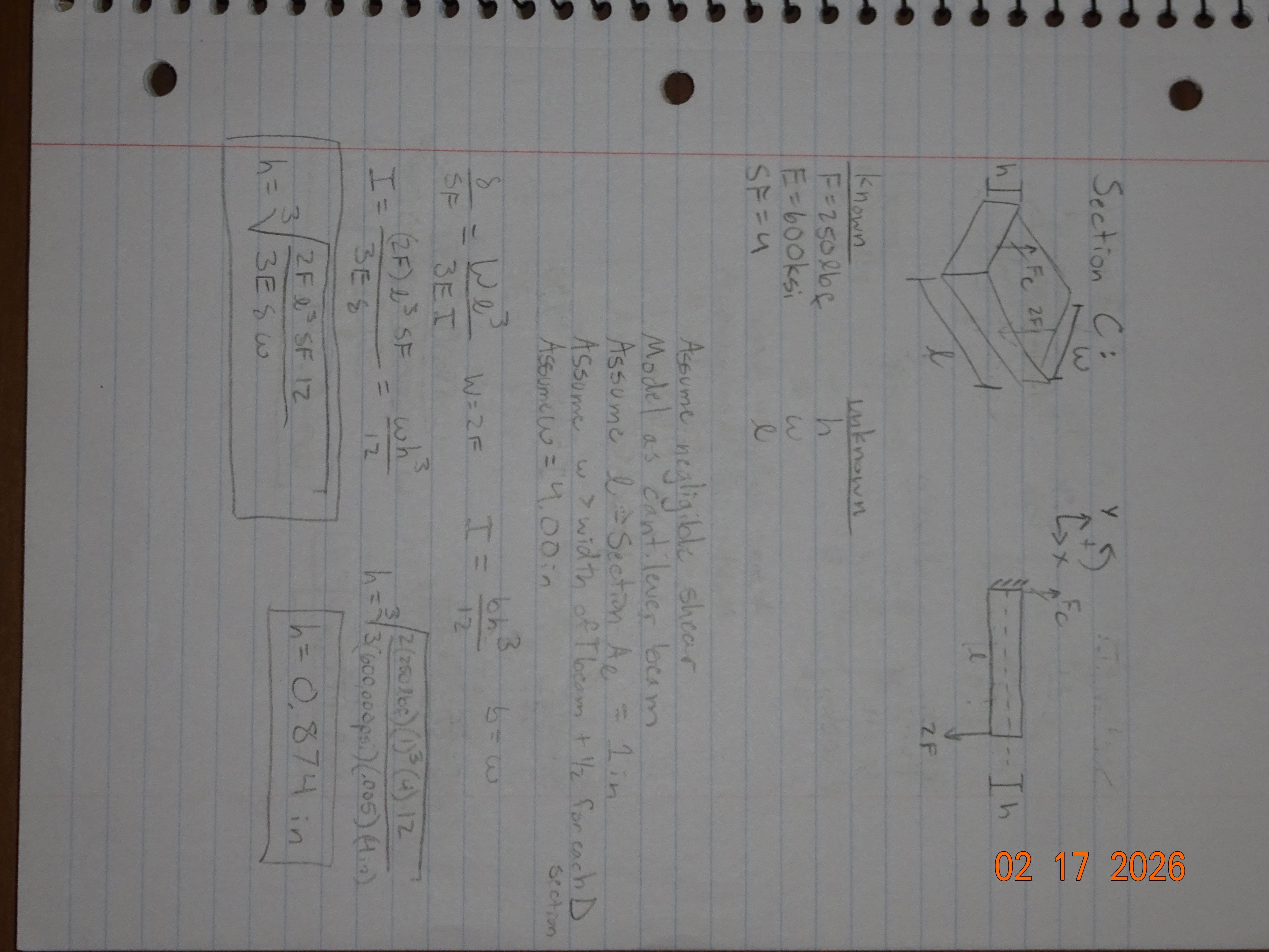
The final dimensions of Stiffness Analysis: Section C --- width = 4 inches, length = 1 inch, height = 0.874 inches
Section D:
Section D is again modeled as a cantilever beam with a distributed load.
Known:
- Force = 250 pounds of force
- Modulus of Elasticity = 600 ksi
- max deflection = 0.005 inches
- Safety Factor = 4
Unknown:
- Width 'w'
- Length 'l'
- Height 'h'
Assumptions:
- Shear deflection is negligible
- Length = 1 inch
- Height = 0.60 inches
- Target w < 0.5 inches
Again, the width is being limited to 0.5 inches to ensure room for the T-beam flange. Fortunately, the calculated value of the width was less than half an inch by about 0.15 inches. This is one of the few calculated dimensions that is smaller than the stress analysis.
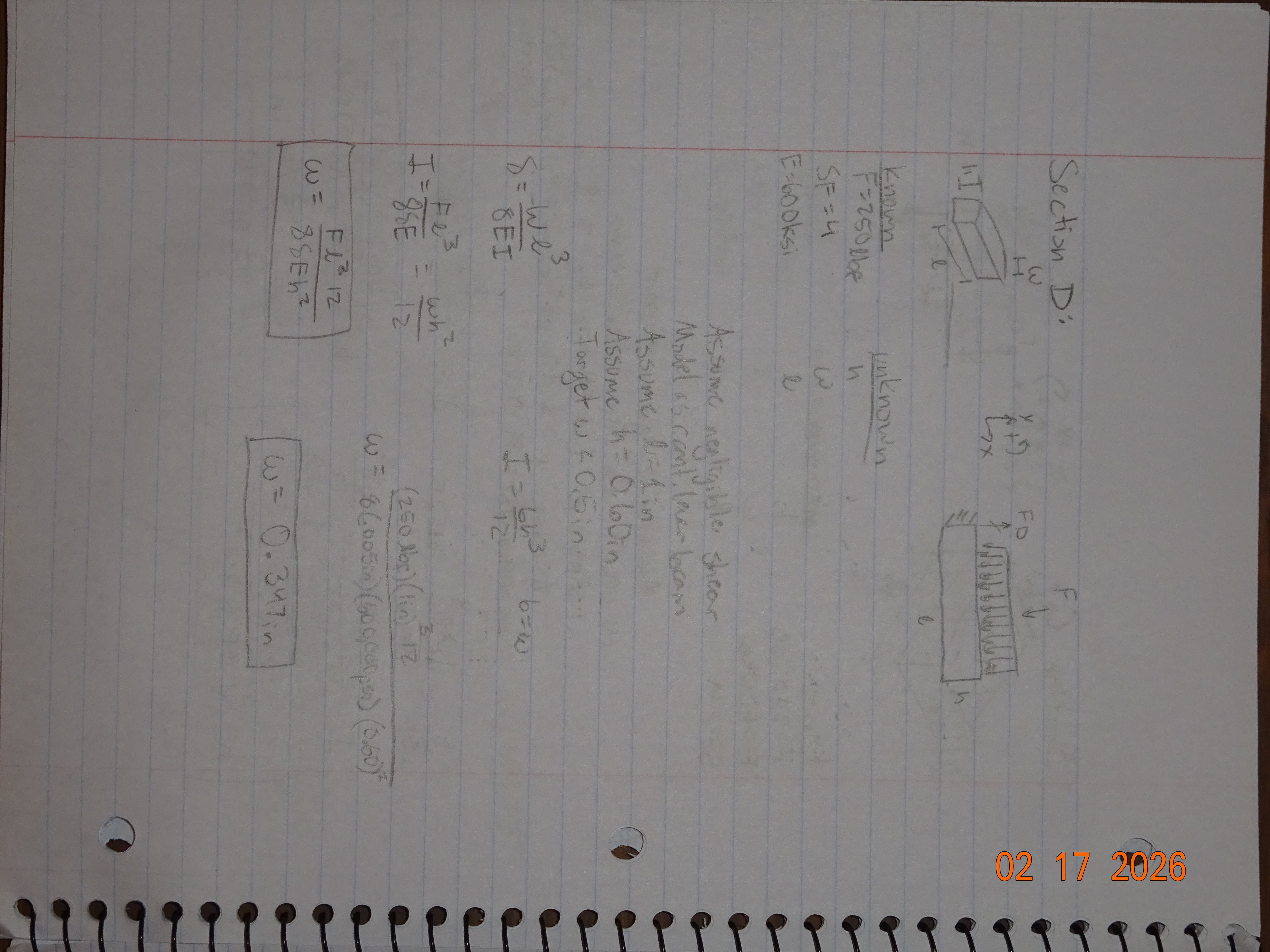
The final dimensions of Stiffness Analysis: Section D --- length = 1 inch, height = 0.60 inches, w = 0.347 inches
Section E:
Section E is again modeled as a cantilever beam with a span length equal to the width of section D. The final width of the section will have an additional 1 inch that comes from the value of the flange width on each side.
Known:
- Force = 250 pounds of force
- Modulus of Elasticity = 600 ksi
- max deflection = 0.005 inches
- Safety Factor = 4
Unknown:
- Height 'h'
- Width 'w'
- Length 'l'
Assumptions:
- Shear deflection is negligible
- Length = 1 inch
- Width = 0.347 inches
This left the final value to be calculated as the height of section E.
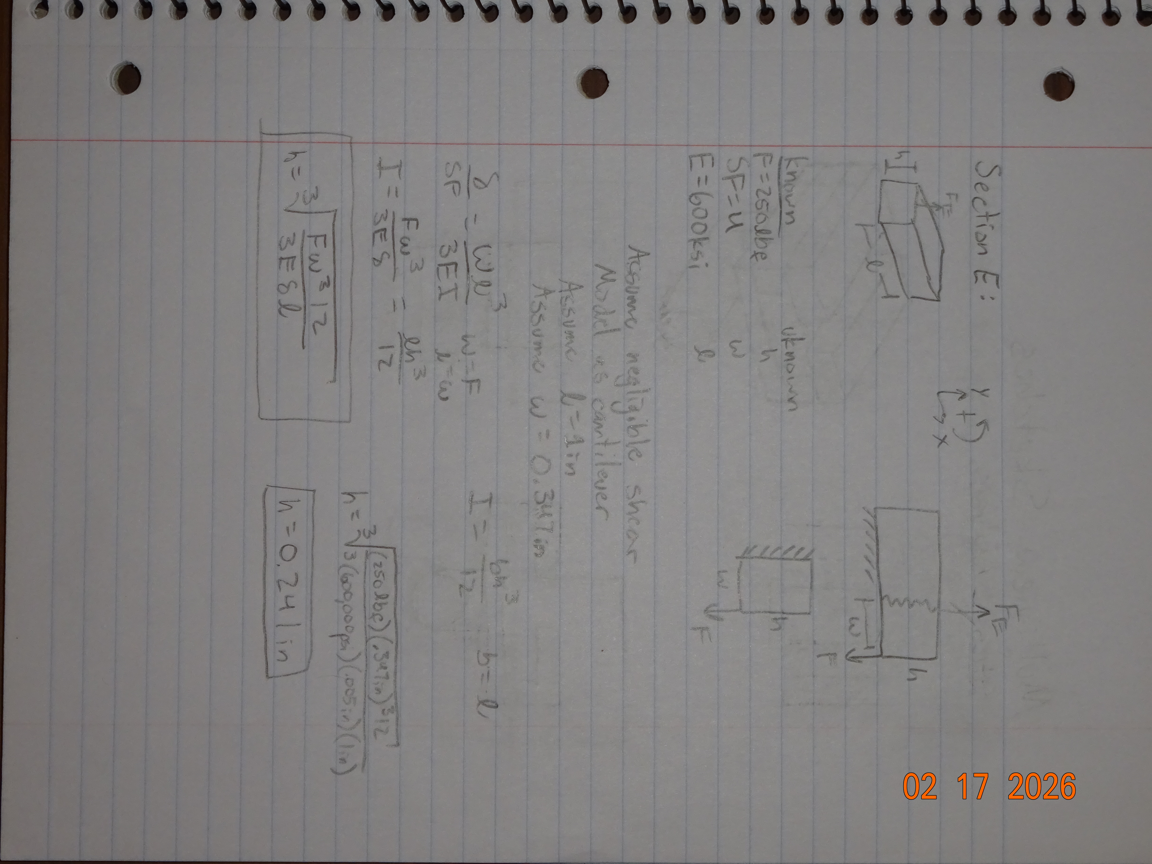
The final dimensions of Stiffness Analysis: Section E --- width = 1.347 inches, length = 1 inch, height = 0.241 inches
Multiview Sketches
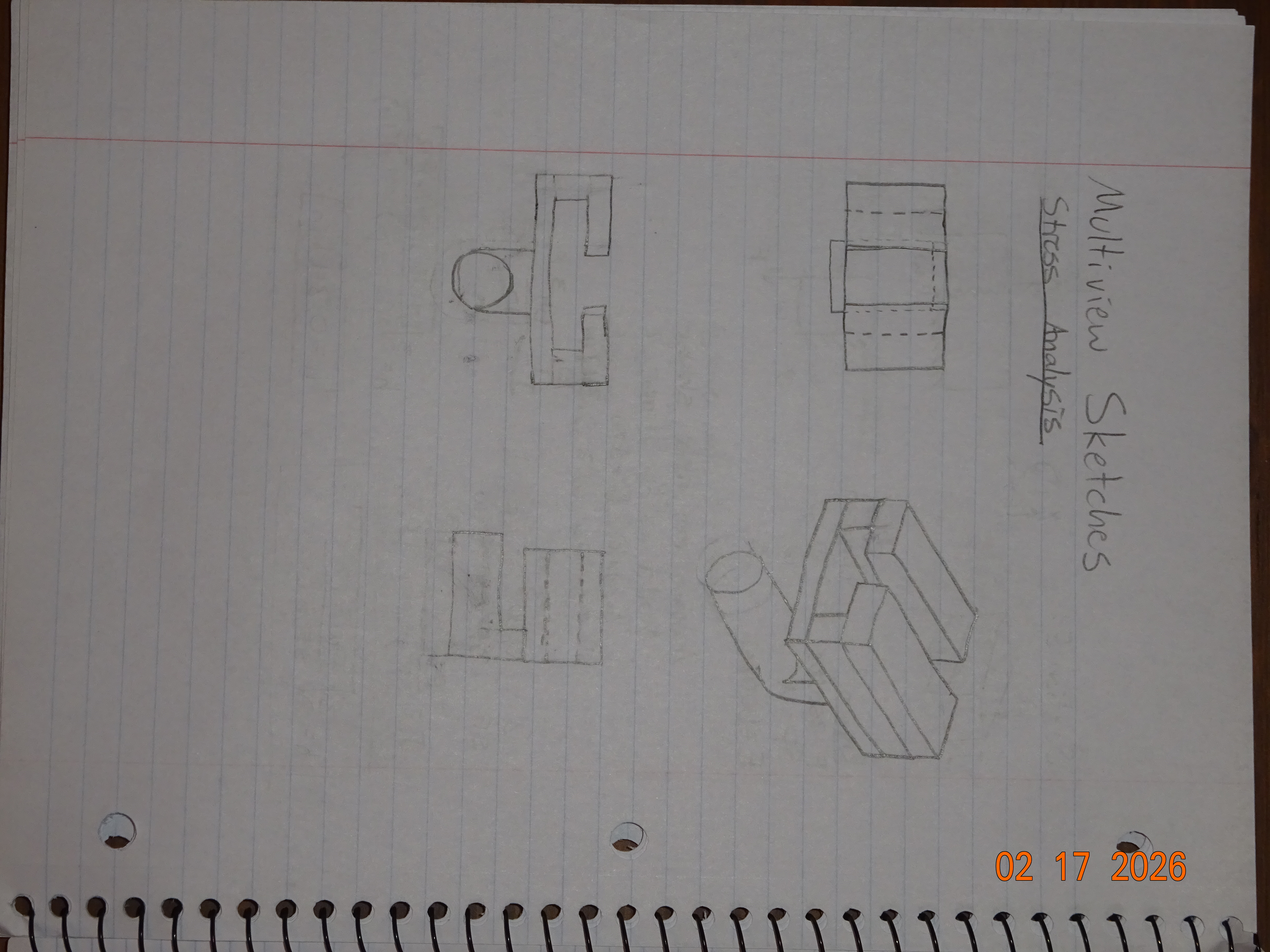
This is the first multiview sketch created from the dimensions of the stress analysis. I did not specifically write in the dimensions, but I tried my best to make sure that the dimensions were relatively accurate. You can clearly see the slot for the T-beam to slot into and the clearance created by section B between sections A and C for the strap to slide into.
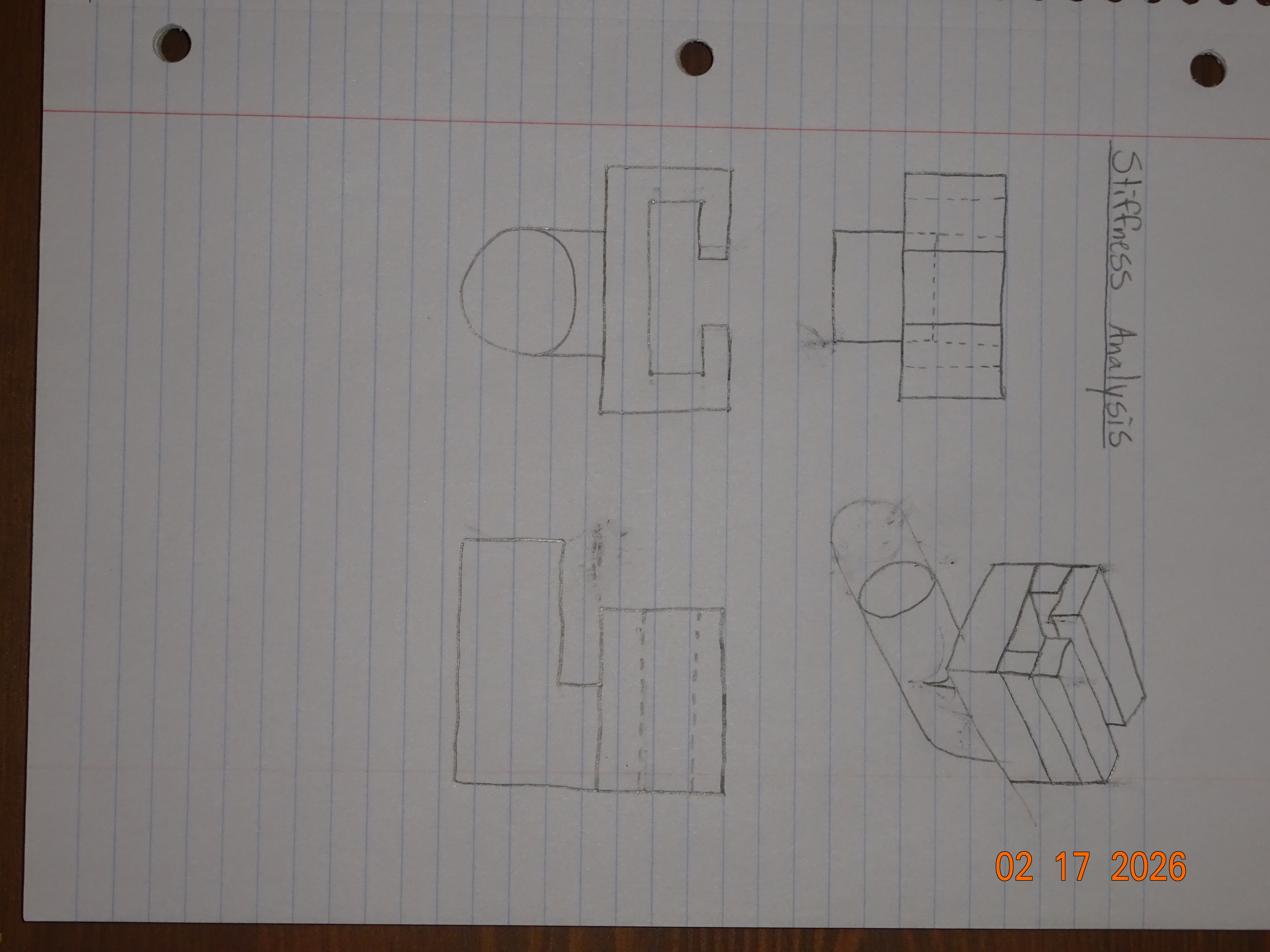
The multiview sketch for stiffness was more difficult for me to visualize due to the depth of section B. I did not include dimensions of the sketches, but I did my best to keep the dimensions relatively accurate in respect to each other. At least based on my sketches, the stiffness analysis provides much larger calculated dimensions than the stress analysis, although a few of the dimensions are smaller.
What this means practically is that the stiffness dimensions would be preferred in a final design since they would be able to support the stress concentration as well as the stiffness.
Lessons Learned
A big lesson from this assignment was that picking the model for sections is difficult. It pays to spend time beforehand to determine which model would be most accurate. The results that I calculated were also a good lesson that the assumed dimensions or constraints for dimensions should be carefully thought through especially when it comes to how you want your calculated value to come out. If I were to go back through this assignment, I would say that those are the two parts that I would want to pay more attention to and spend more time on. In the future, I hope to be more diligent in selecting accurate models and assumptions and paying more attention to how my assumed constraints affect the calculated values.
Time Spent:
In total, I would estimate that about 7-8 hours were spent doing the calculations and creating the portfolio for this assignment.
PDF of Work:
Here is the link to a downloadable copy of my complete hand written work.