
FEA on Bracket
Assignment Objectives:
- Use Finite Element Analysis (FEA) to improve the bracket design from previous assignments.
- Ensure high stiffness, strength, and lightweight optimization through iterative design.
- Conduct multiple FEA simulations, refining geometry based on results.
- Perform static stress analysis, including constraints, loading, and meshing selection.
- Interpret data by identifying max stress, displacement, and safety factors.
- Optimize the design by modifying geometry to enhance performance.
- Document the entire process with images, calculations, and insights.
- Reflect on key engineering lessons learned and time spent.
Assignment Description:
Your task is simply to create a high stiff, high strength, and lightweight component. Use Finite Element analysis to drive your decision making process throughout your design. Each step of the analysis and before you make geometric changes make sure the component’s results (stress/displacement/Safety Factor) converge on a 7% difference. Achieve this by modifying the number of elements. If after three attempts to converge use the stiffness and stress from the finer mesh size.
*Note: Assignment Objectives and Description come directly from Dr. Fagan's assignment.
Design Iterations:
Design 1:
This iterations starts with the previous design from Assignments 5 and 6. I made some small adjustments during Assignment 6, so I will be starting from my most recent finalized model. As a reminder, this bracket slides onto a fixed T beam and is to support a strap with a load of 200 to 300 lbf from each end as seen in Figure 1. Our target safety factor is 4 and the material I selected was the Torlon® PAI which has a yield strength of 20 ksi. Assignment 5 also defined the max deflection as 0.005 inches as our target.
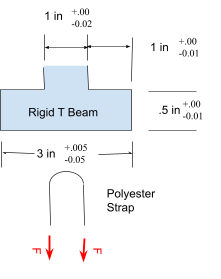
Figure 1.) Specification Visual of the rigid body the bracket affixes to and the polyester strap the bracket needs to hold
First, I loaded the bracket in SolidWorks and started a new static study. I then added two fixed planes where the bracket would rest on the T-beam. Since our load is to be between 200 and 300 lbf, I took the max and then doubled it for both ends of the strap which gave me 600 lbf. I placed the force directed downwards on the surface where the strap would be placed on Section A. I then created a mesh with the slider about half way between course and rough. I then ran the study. When adding the factor of safety plot, I was prompted to add a yield strength for my custom material. I went back to the model to and added the yield strength to be the same as the tensile strength. Then I re-ran the simulation.
Here is the setup:
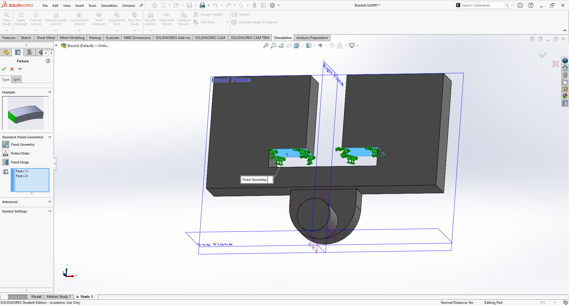
1. Fixed Planes on the Bracket
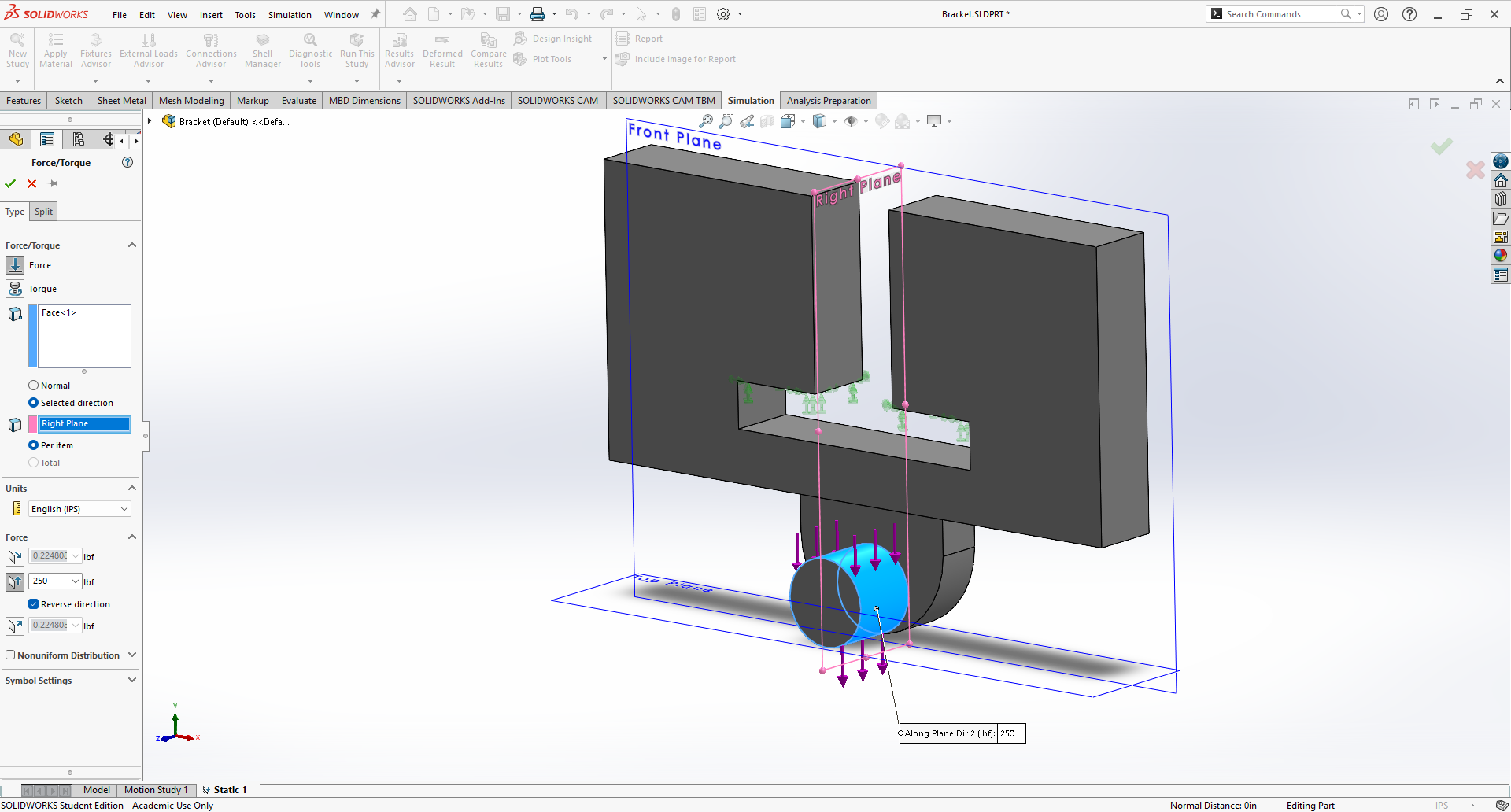
2. Load over Section A
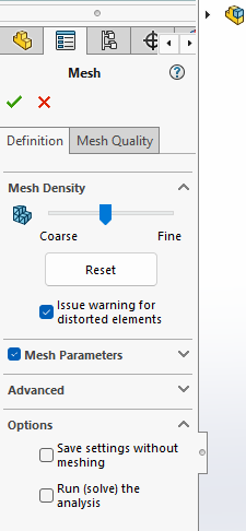
3. Create the mesh
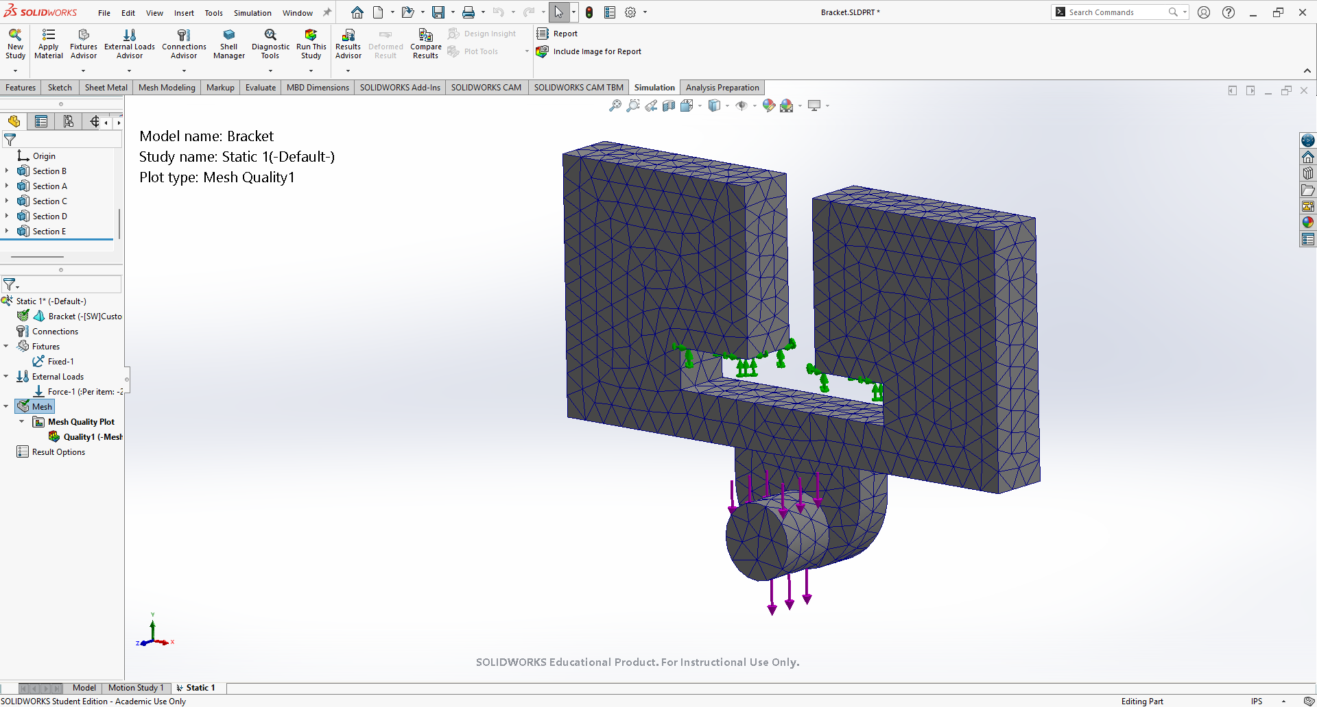
4. Mesh displayed on the model
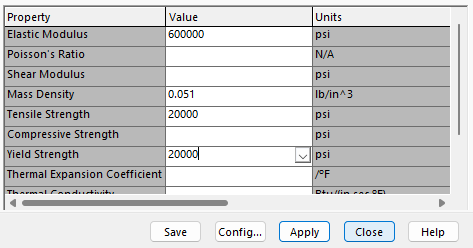
5. Adding Yield Strength to Custom Material
Here are the results:
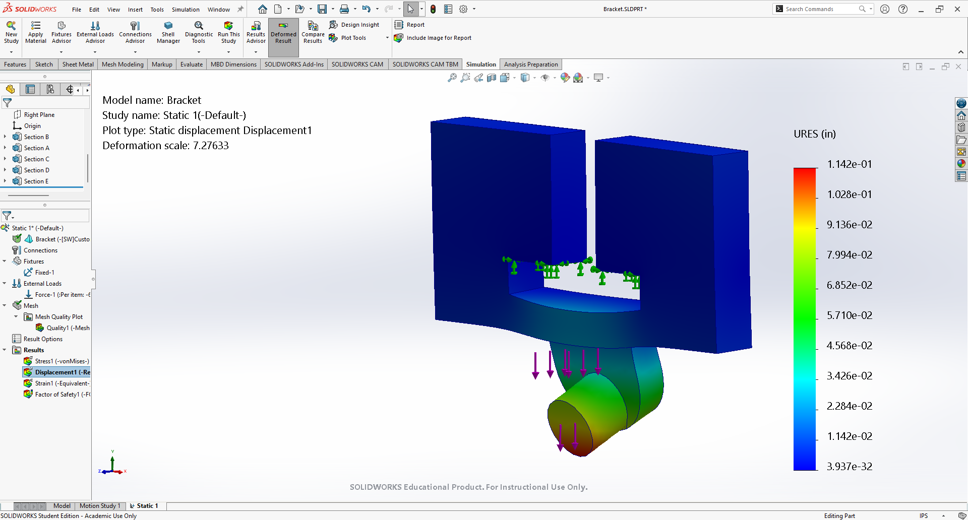
6. Design 1 - Mesh 1 - Deflection
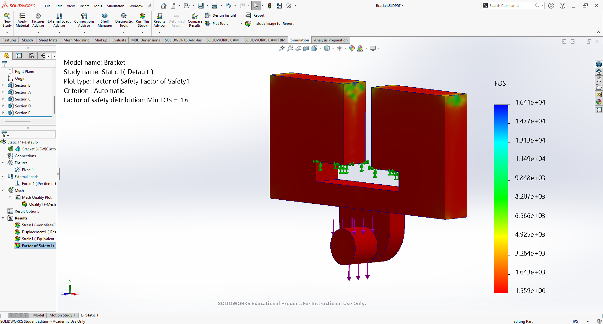
7. Design 1 - Mesh 1 - Safety Factor
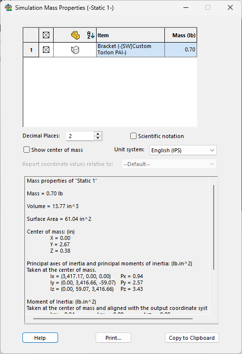
8. Design 1 - Mesh 1 - Mass
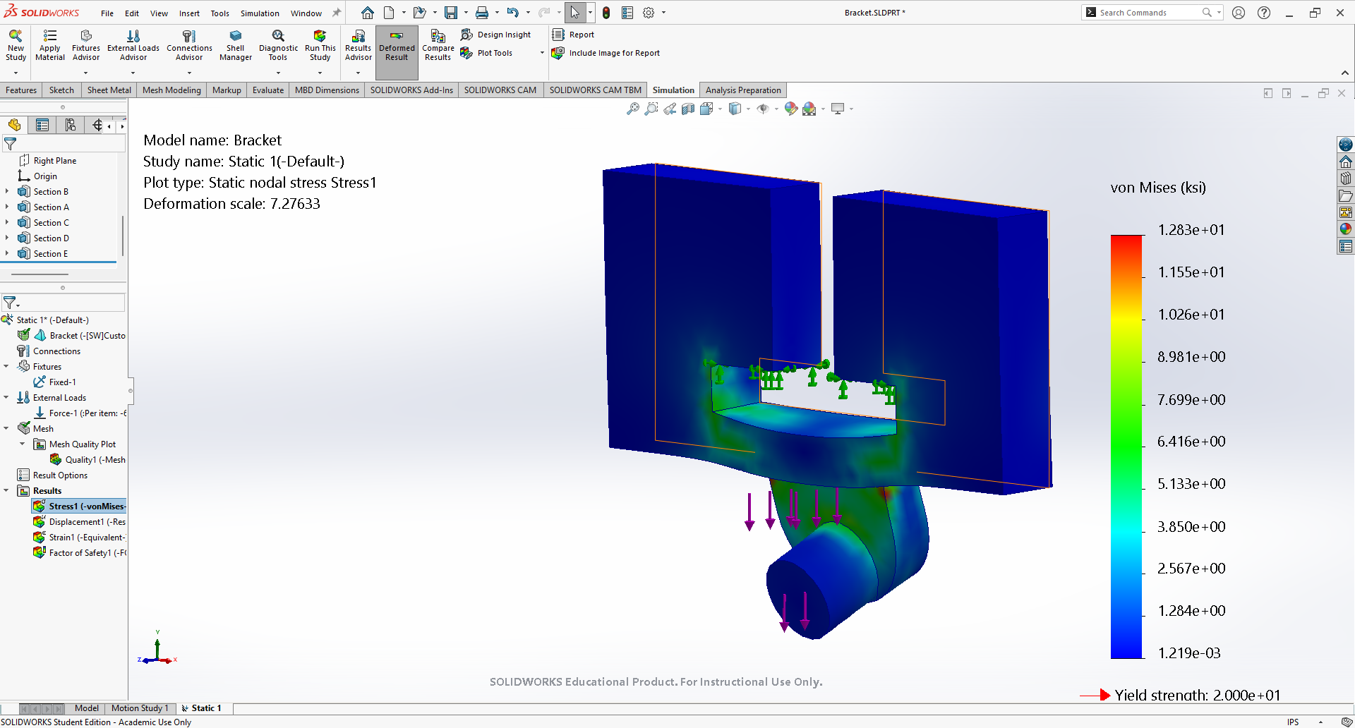
9. Design 1 - Mesh 1 - Stress
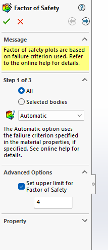
10. Changing how factor of Safety is Displayed
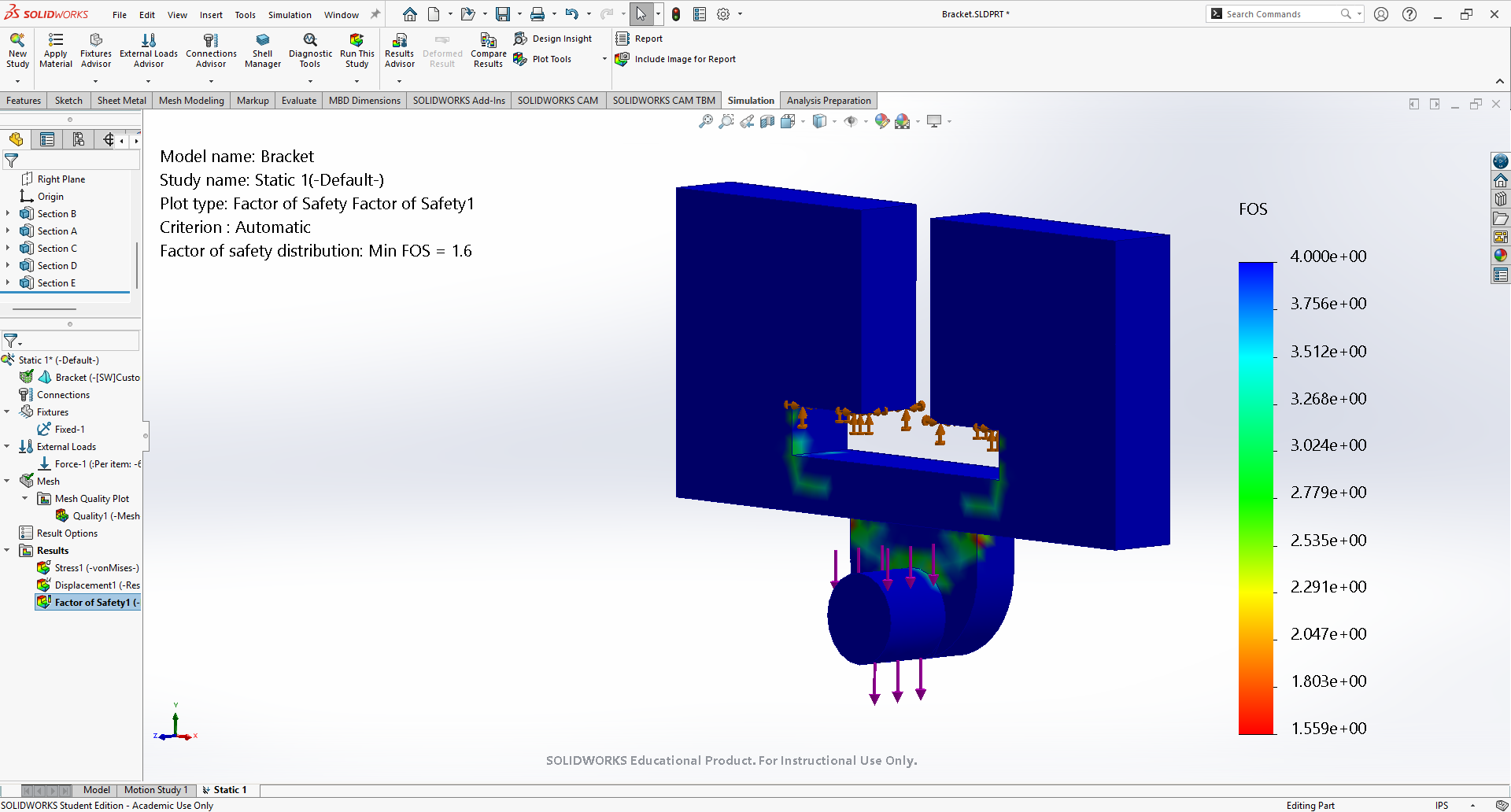
11. Design 1 - Mesh - 1 - Factor of Safety Updated
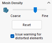
12. Increasing Mesh Density
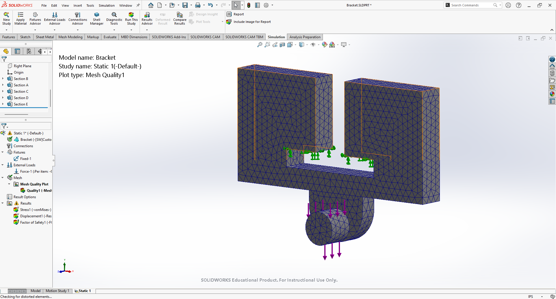
13. Design 1 - Mesh 2
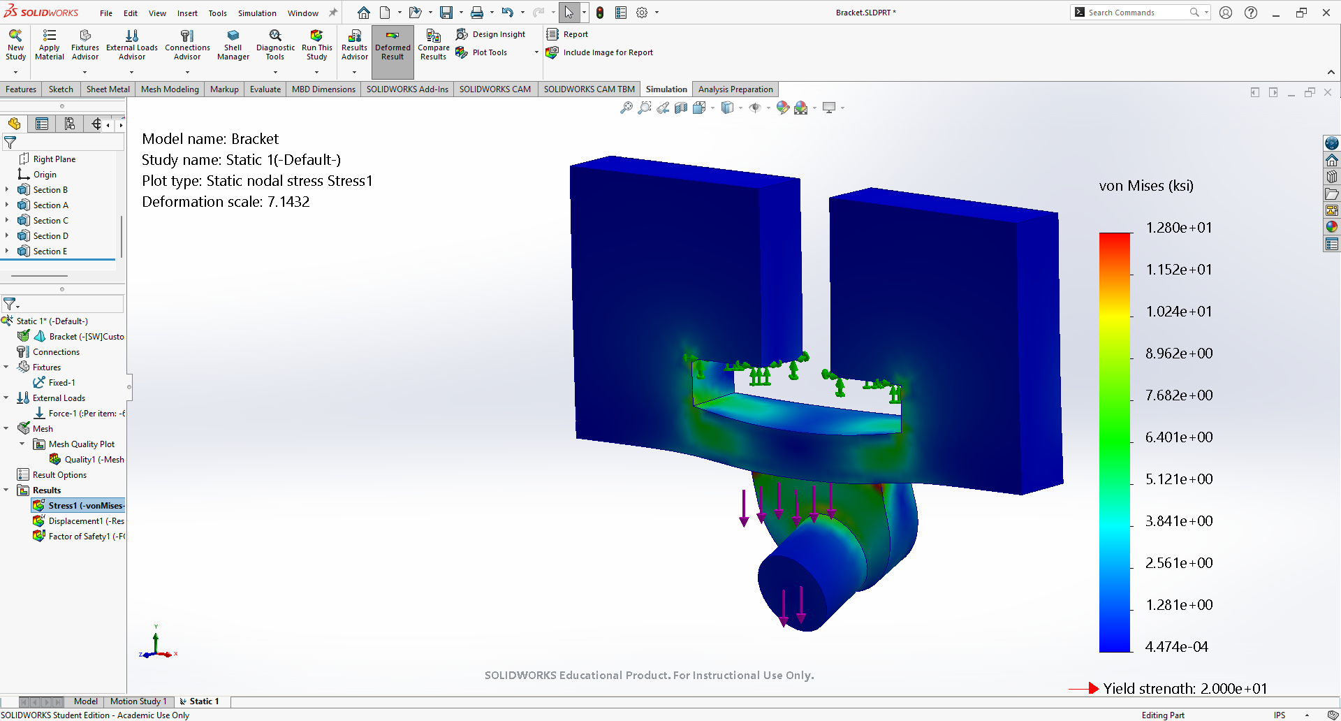
14. Design 1 - Mesh 2 - Stress
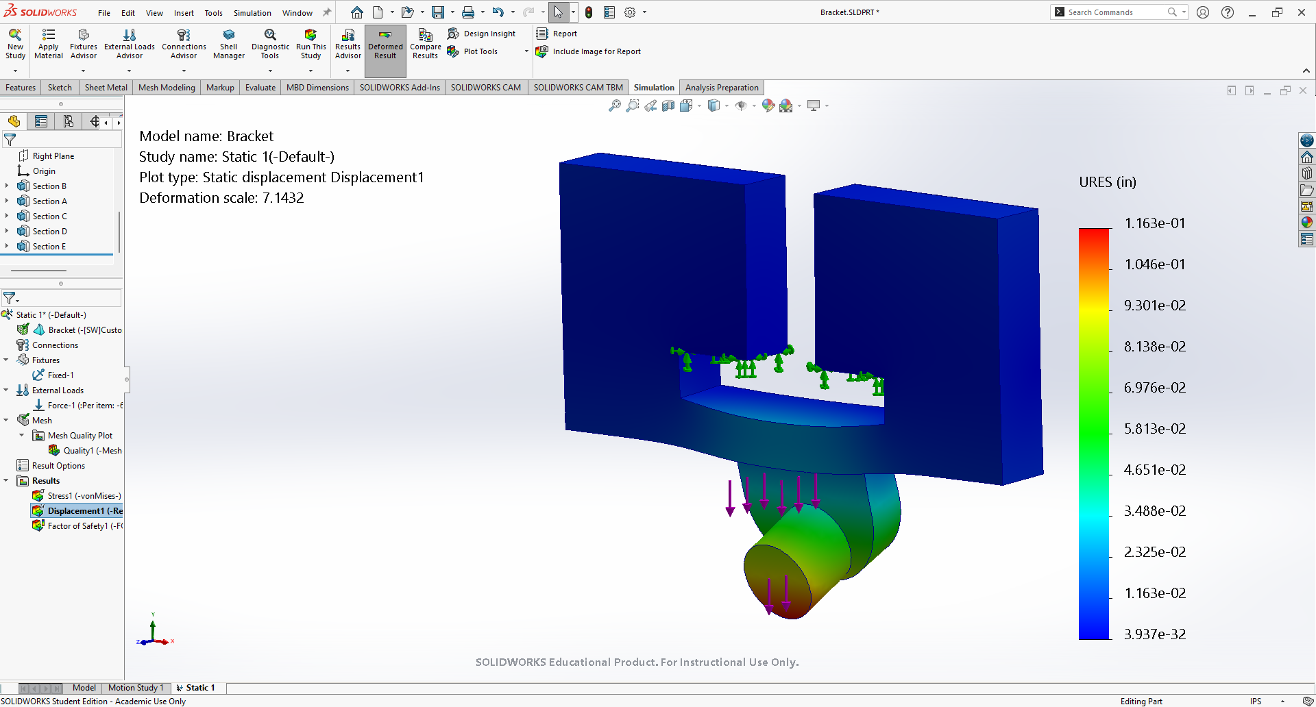
15. Design 1 - Mesh 2 - Deflection
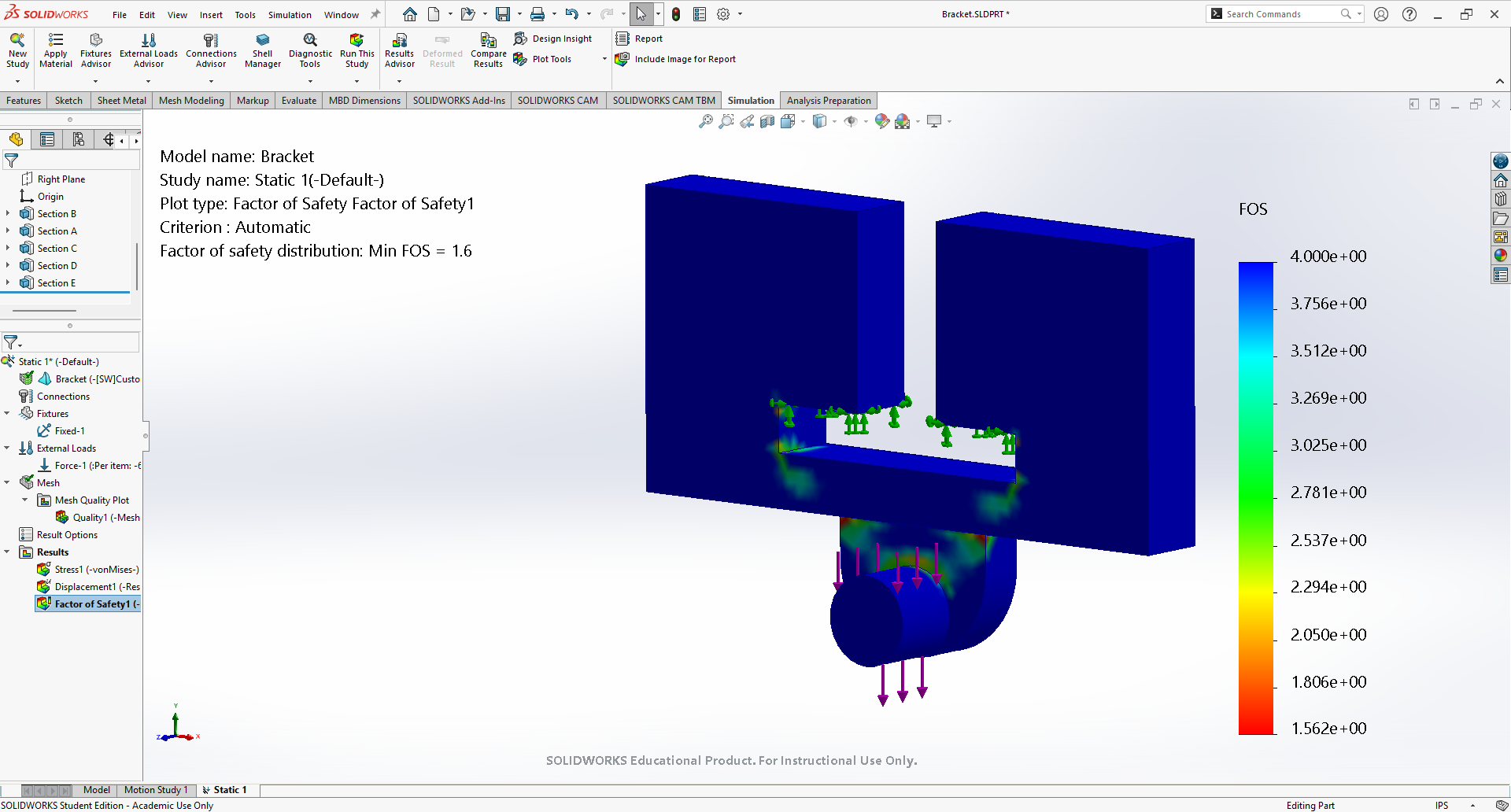
16. Design 1 - Mesh 2 - Safety Factor
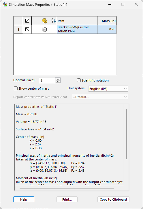
17. Design 1 - Mesh 2 - Mass
The reason why there are two different mesh simulations, is because it is important to test that the two converge to the same results. If they don't, it would mean that something is wrong with either the model, the simulation setup, the parameters, etc. To verify if the two have converged, I used the equation 2(|xf-xi|/(xf+xi)) x 100%. As long as the percentage is less than 7%, I can consider them converging and move on to the next design.
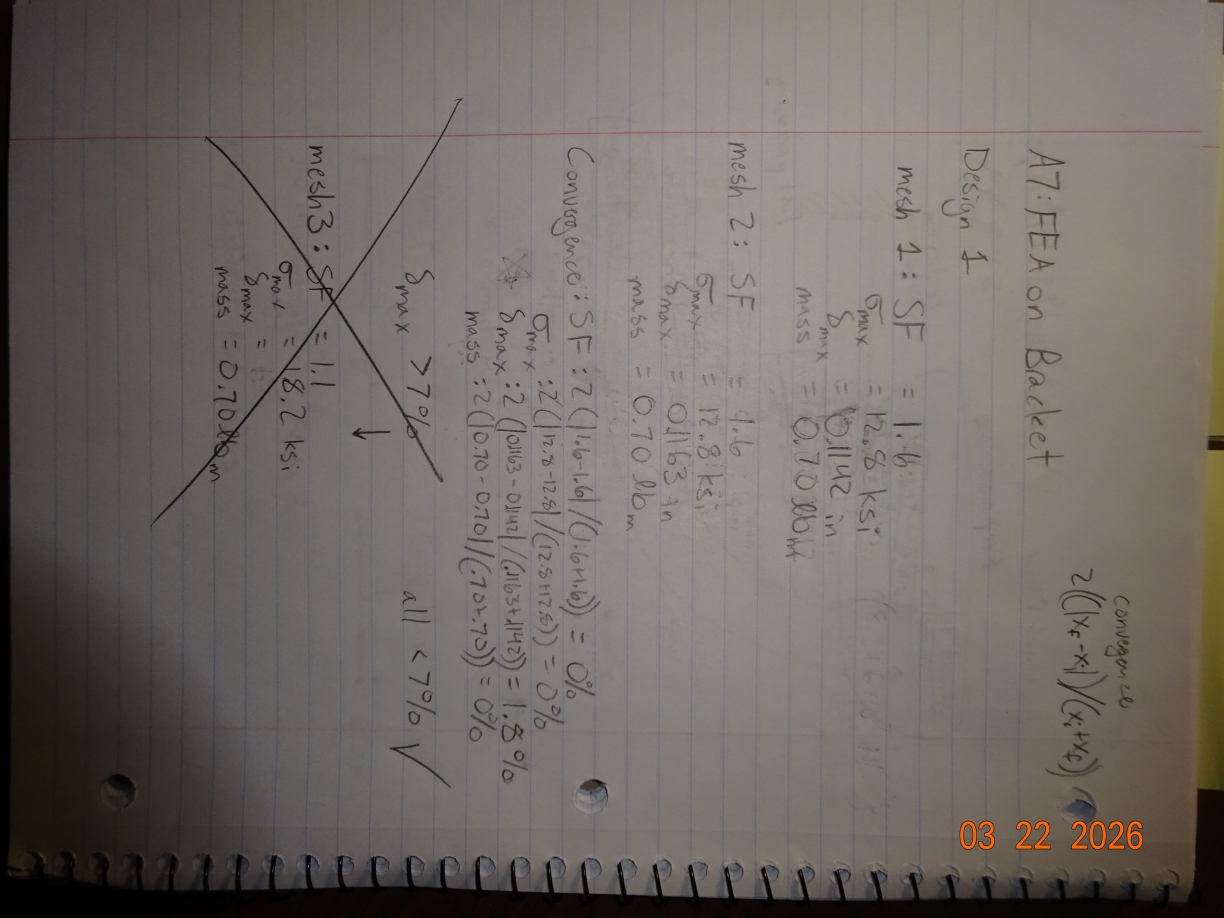
I had accidentally written down the deflections wrong initially, so I thought I would have to do a third mesh. Quickly, I realized that when I was writing the values from scientific notation into their real notation I had missed a "1" which when corrected in the equation, got a percentage well below 7%. After verifying convergence, I can use the finer mesh's values to begin filling out my design iteration table. Then I can work to identify where to improve the original design. Unfortunately, I realized too late that I had not tracked the element size for each simulation result. I had already overwritten my finer mesh size from Design 1, so the data in the table will come from the first mesh (the default mesh size). The other two designs however, will utilize their last mesh for the values, since I did save their last simulation results.
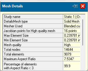
18. Design 1 - Mesh 1 - Number of Elements
| Design 1 | |
| Max Stress and Location | 12.8 ksi at the top corners of Section B as they connect to Section C |
| Max Deflection and Location | 0.1142 inches at bottom of Section A |
| Mass | 0.70 lb |
| Safety Factor | 1.6 |
| Number of Elements | 9079 |
Design 2:
The two main concerns I observed in the first design, were the high stress concentration at the point where Section B meets Section C (seen in images #9 and #14), and then the excess amount of low stress and deflection within the majority of the upper sections. To try and optimize these locations, I first went in and added a round on Section B to hopefully prevent some of the large concentrations of stress there, I used the default round size of 0.1 inches.
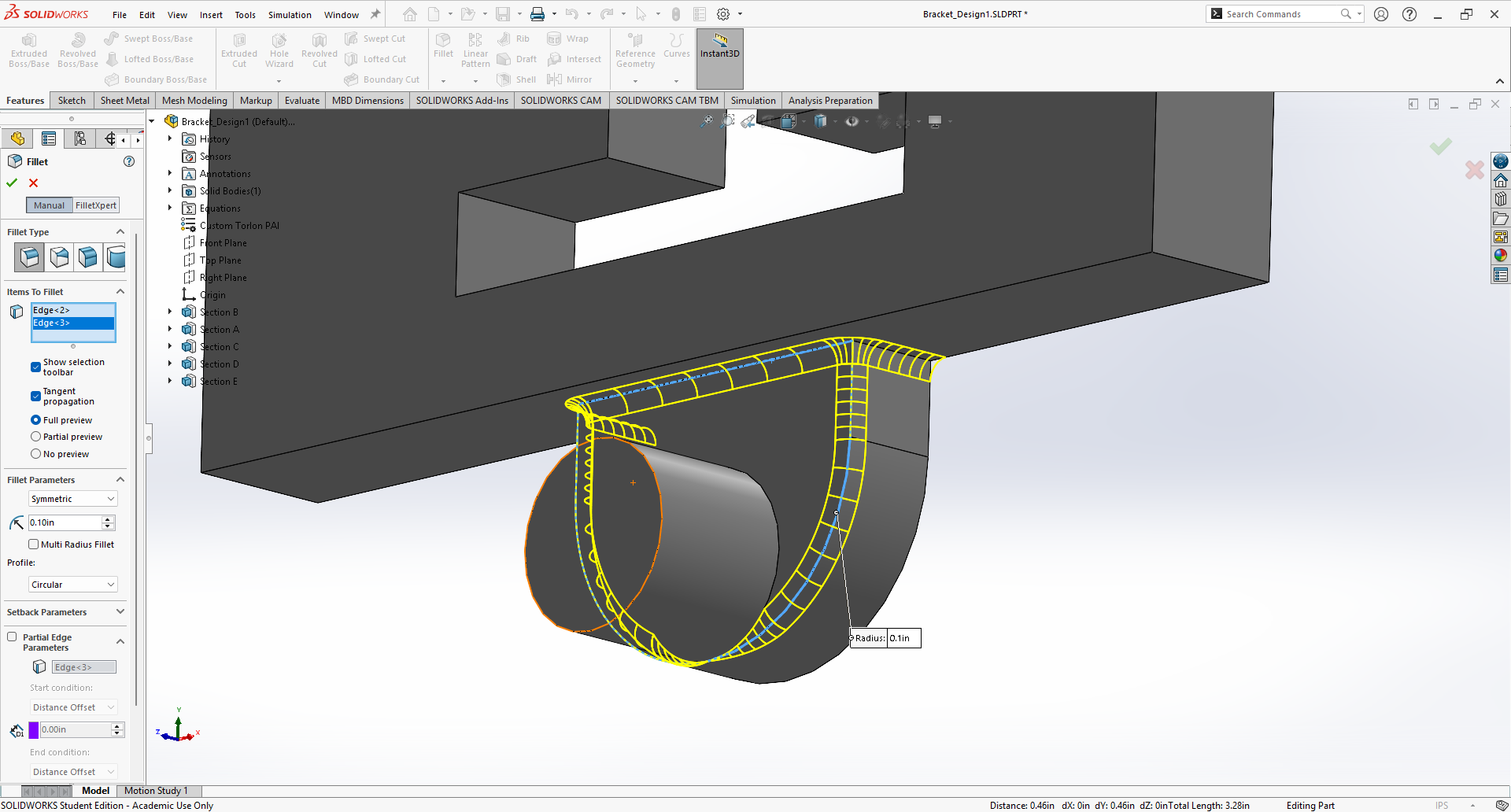
19. Adding Round to Section B
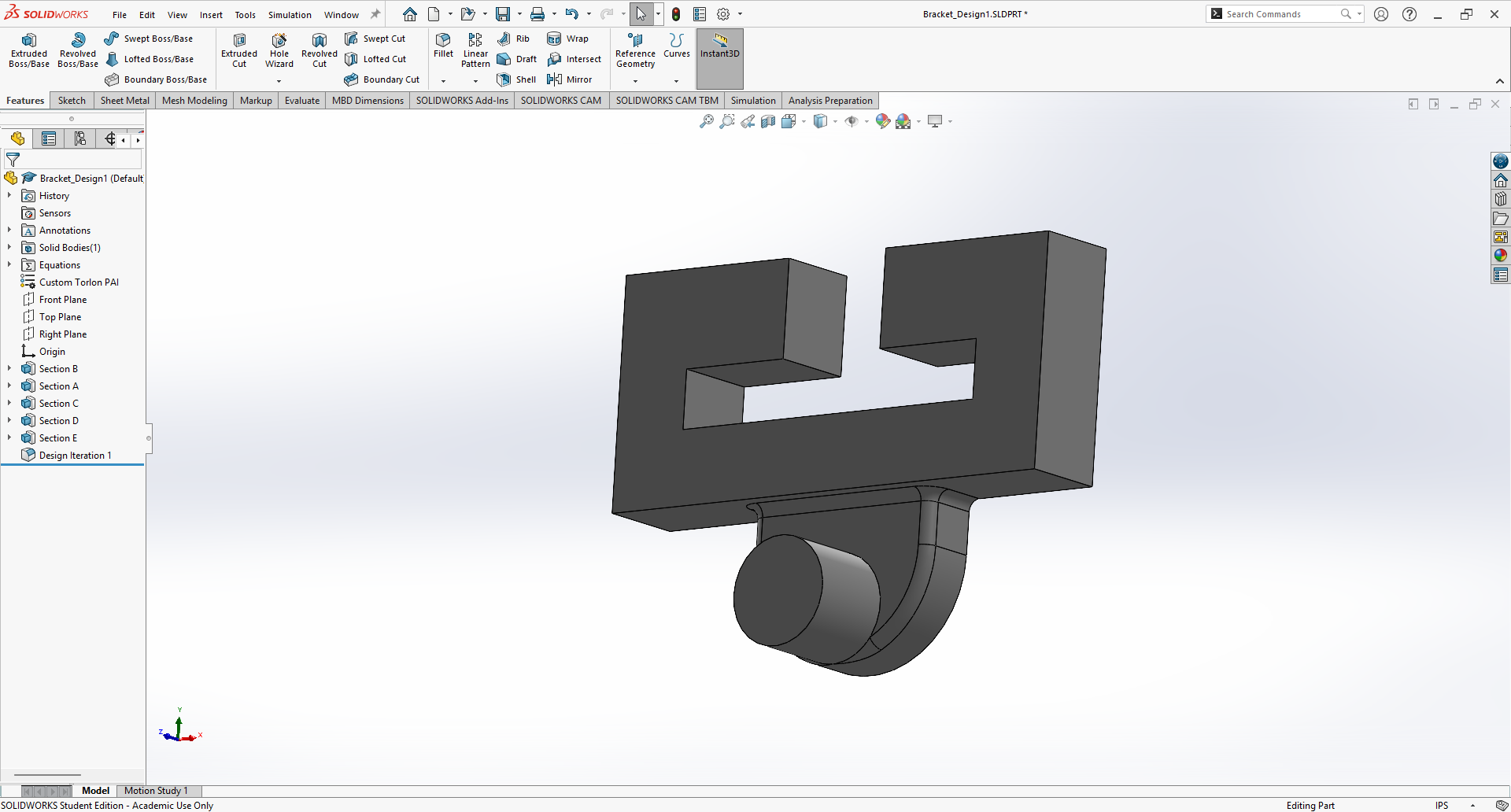
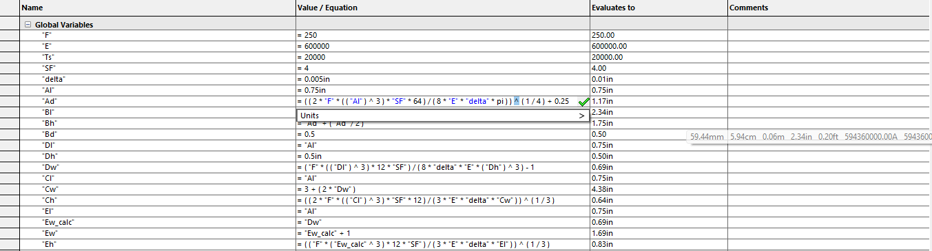
The second change I made was to the dimension sizes for sections C, D, and E. I started by shortening the height of E, by subtracting 1 inch from the calculated value in the equation tab. The widths for the sections were all found in relationship to the width of D, so I subtracted 1 inch from the D width in the equation tab as well. The final change I would make is increasing the diameter of Section A in the hopes of reducing some of the deflection.
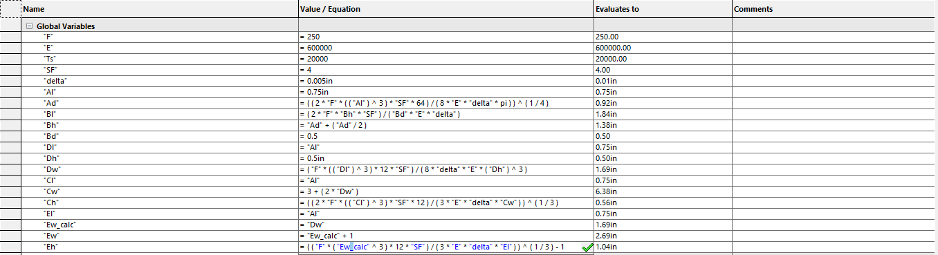
20. Changing the Equation for Section E height
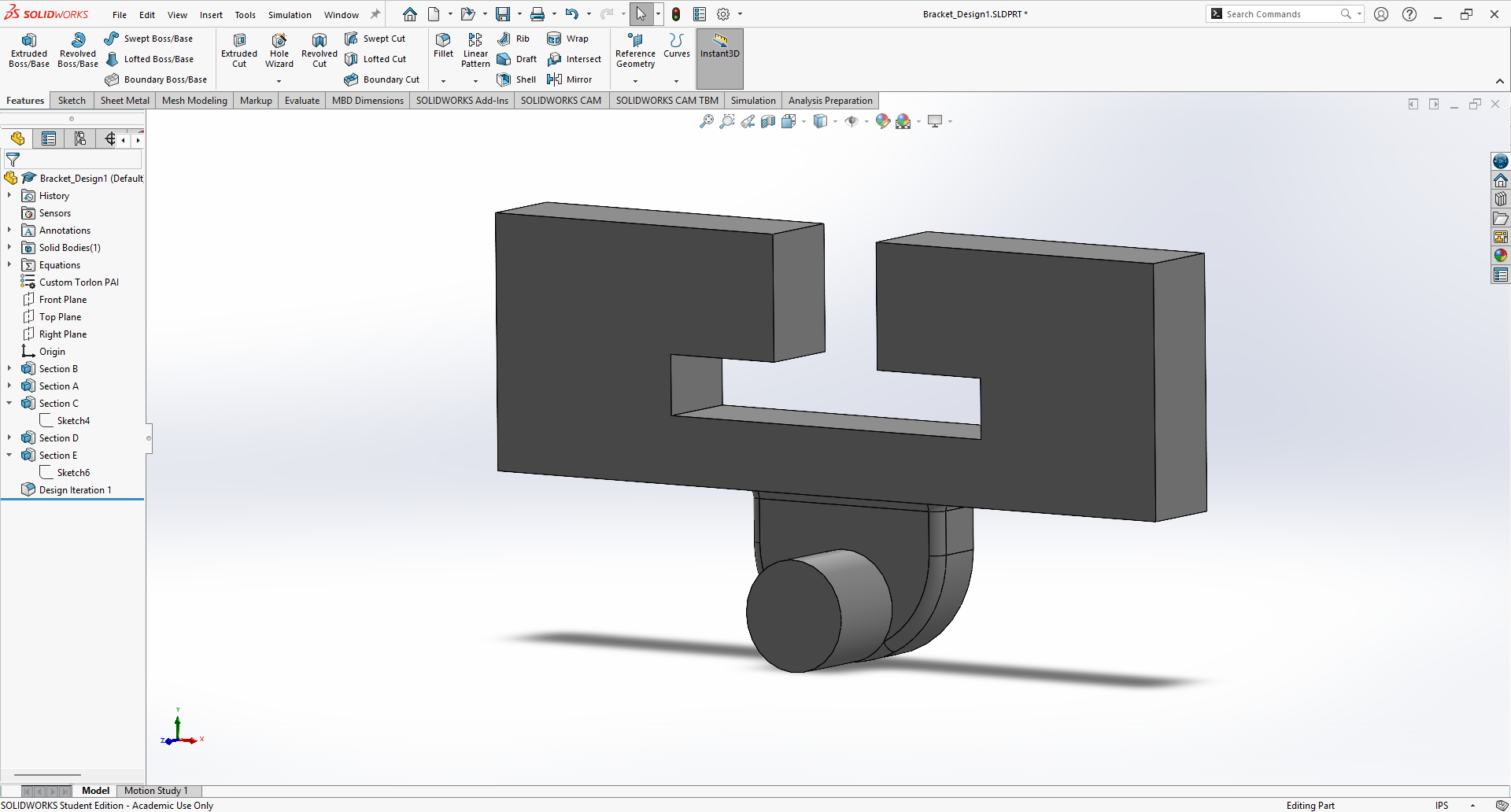
21. Model after Updated Height
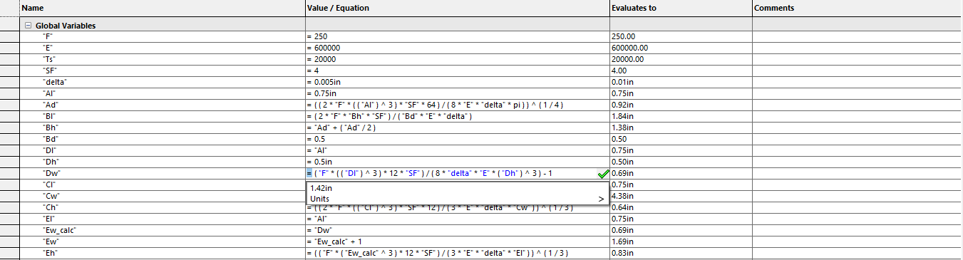
22. Changing the Equation for Section D width
23. Model after Updated width
24. Changing Section A in equation tab
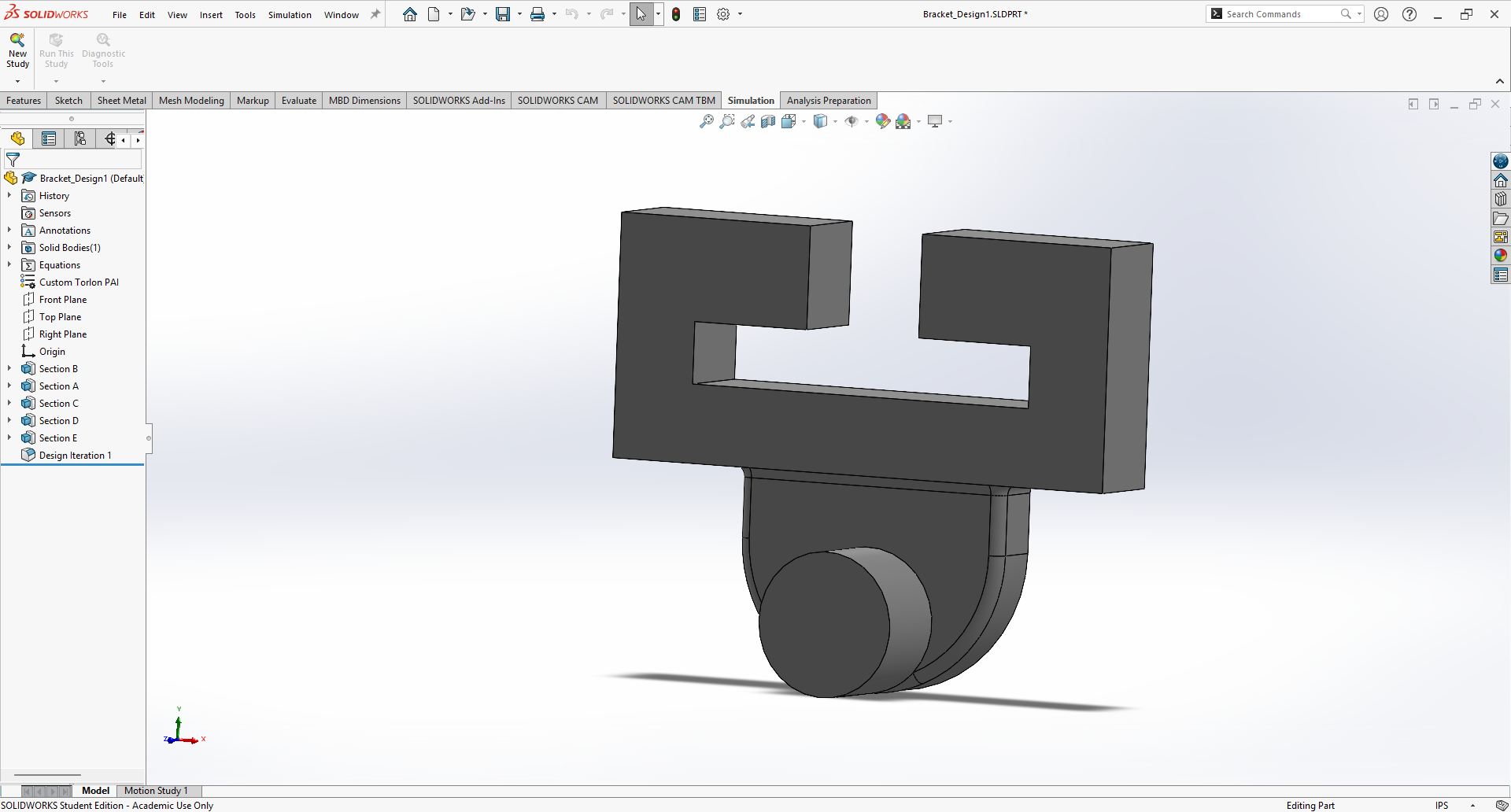
25. Model with Updated Diameter
Design 2 Model
With my changes done, I am able to create a new simulation with a new mesh to hopefully yield better results than Design 1. The process is the same as the last, and I utilize the same fixture planes and load. Below are the results.
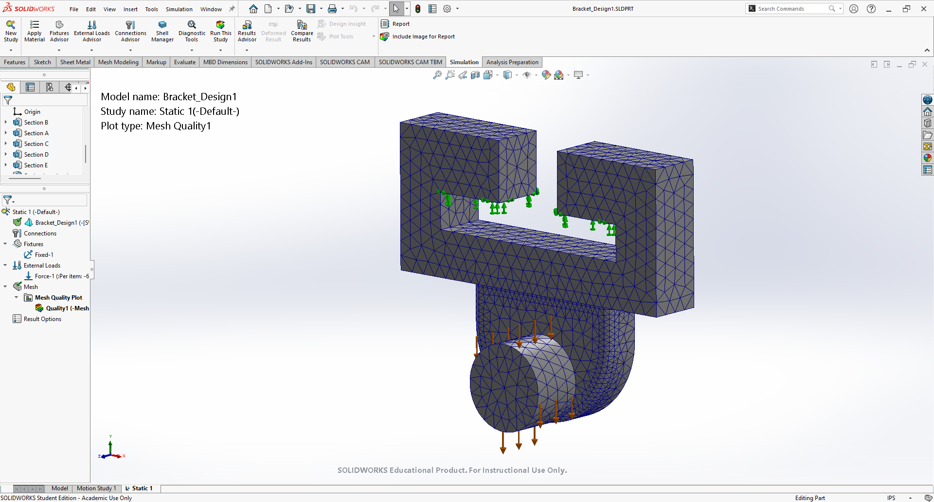
26. Design 2 - Mesh 1
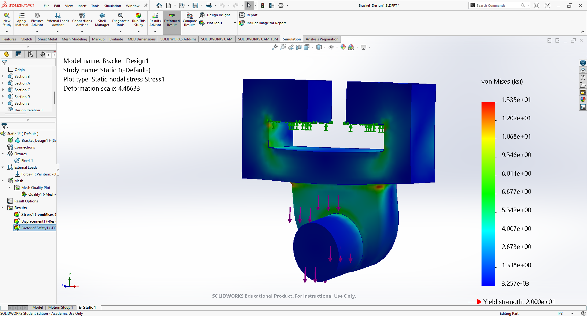
27. Design 2 - Mesh 1 - Stress
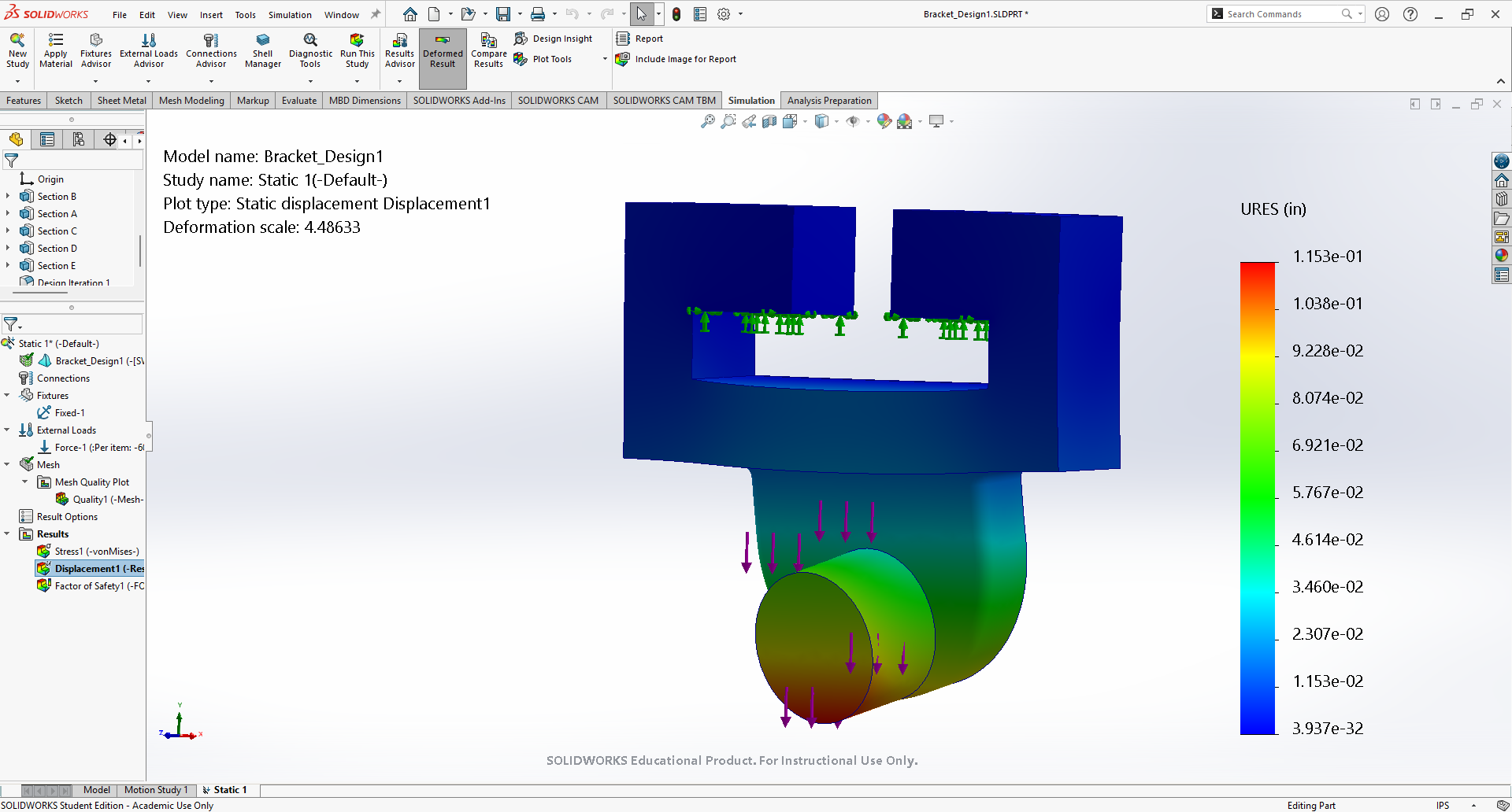
28. Design 2 - Mesh 1 - Deflection
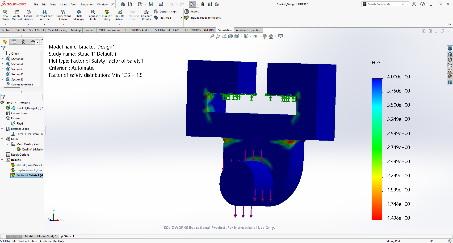
29. Design 2 - Mesh 1 - Factor of Safety
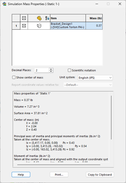
30. Design 2 - Mesh 1 - Mass
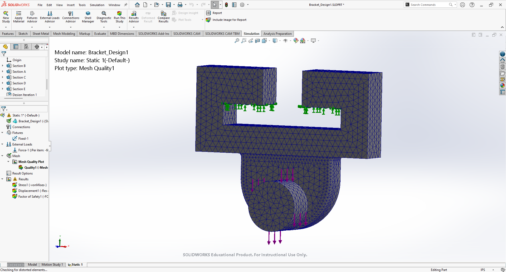
31. Design 2 - Mesh 2
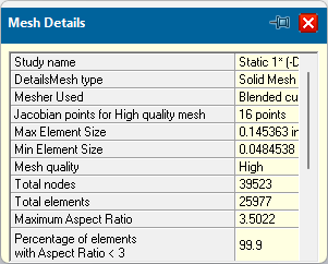
32. Design 2 - Mesh 2 - Number of Elements
The results for the finer mesh size were roughly the same as for the first mesh, but I still had to calculate their percent differences to verify convergence.
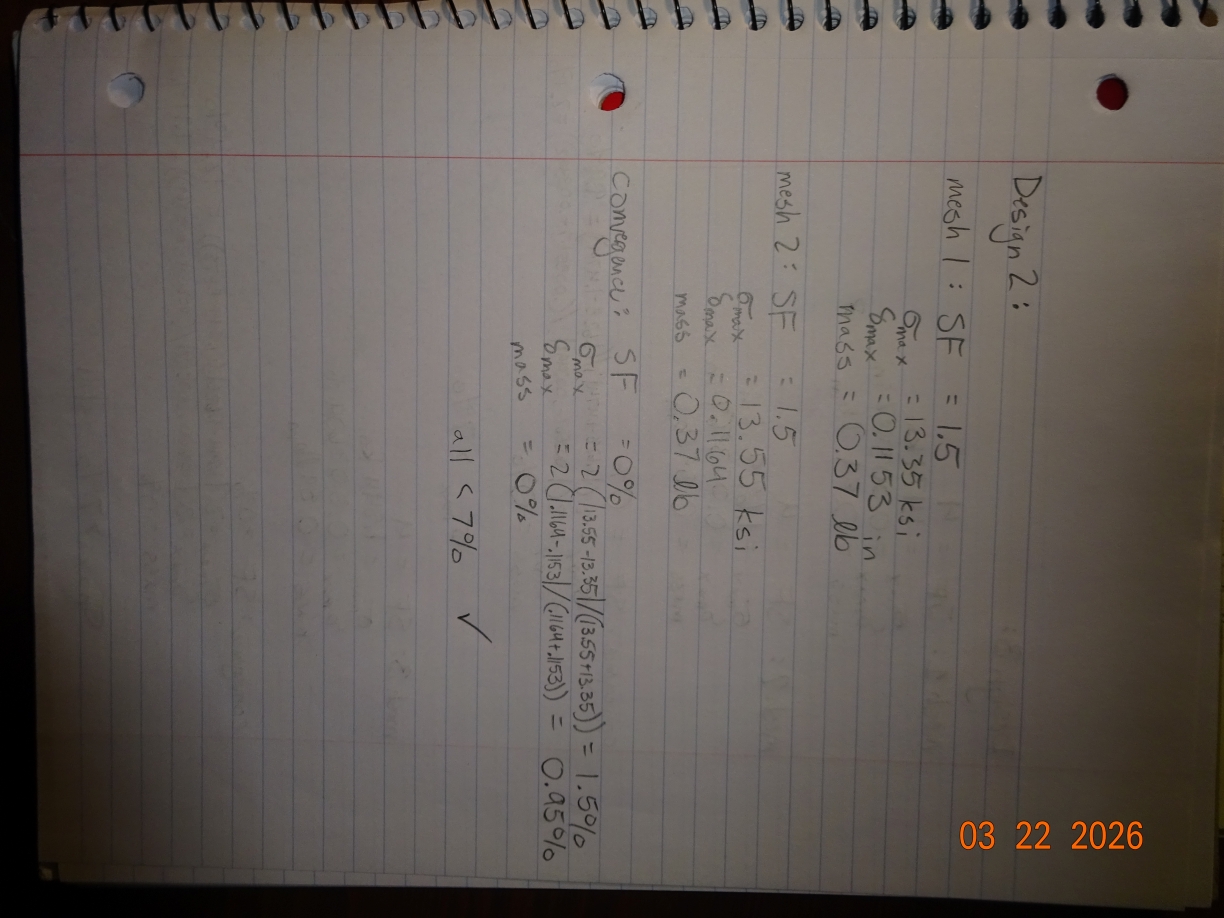
The values were all less than 7%, so I continued. The next task is to continue filling out the table. For design two, I use the data associated with the second, finer mesh size.
| Design 1 | Design 2 | |
| Max Stress and Location | 12.8 ksi at the top corners of Section B as they connect to Section C | 13.55 ksi at the top corners of Section B as they connect to Section C |
| Max Deflection and Location | 0.1142 inches at bottom of Section A | 0.1164 inches at bottom of Section A |
| Mass | 0.70 lb | 0.37 lb |
| Safety Factor | 1.6 | 1.5 |
| Number of Elements | 9079 | 25977 |
Design 3
At this point, I was still missing two of my four target criteria. My deflection was still much much higher than it was supposed to and the max stress, while still being under the max allowed stress, was creating a much lower minimum factor of safety. Since the next design would ideally be my last revisions to the part, I decided to take a closer look at the FEA results.
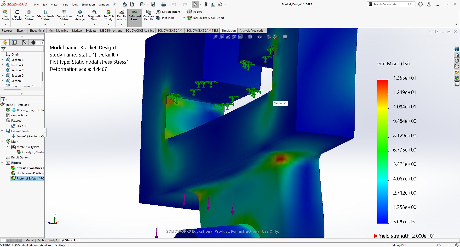
33. Close Up of Max Stress - Design 2
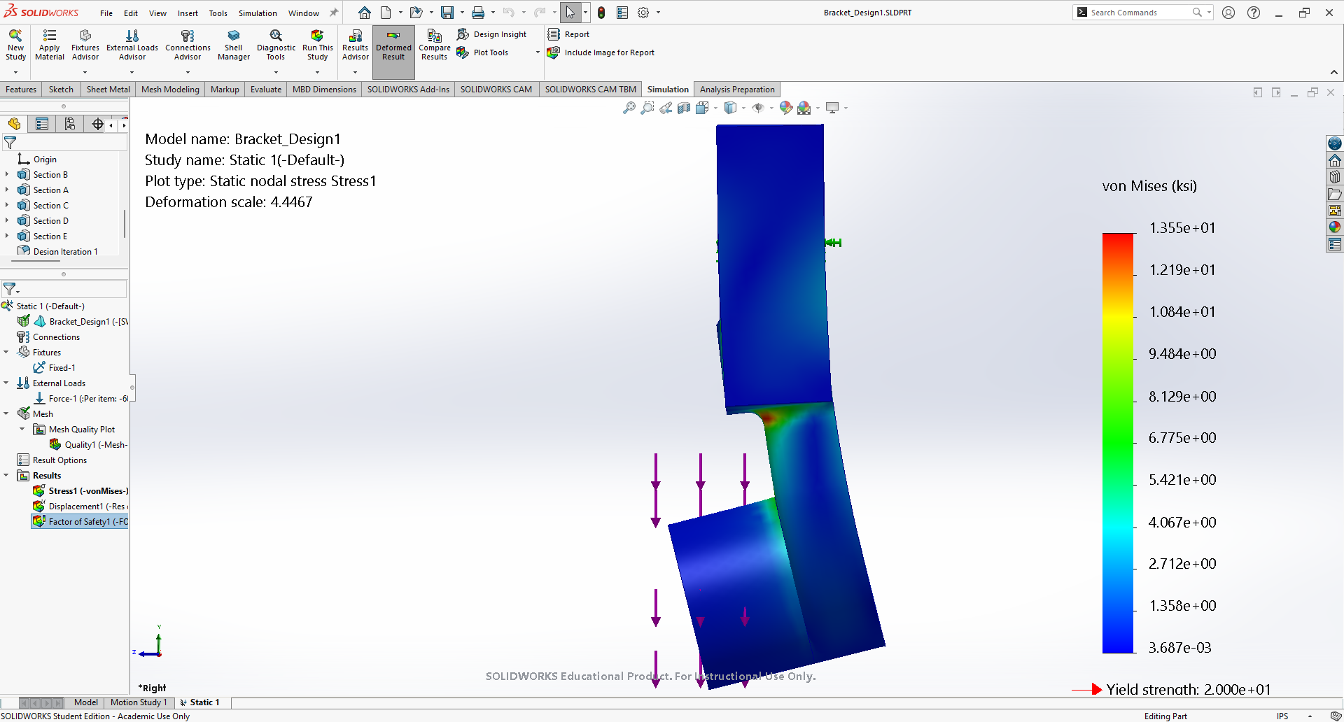
34. Side View of Stress (Scale:4.4467) - Design 2
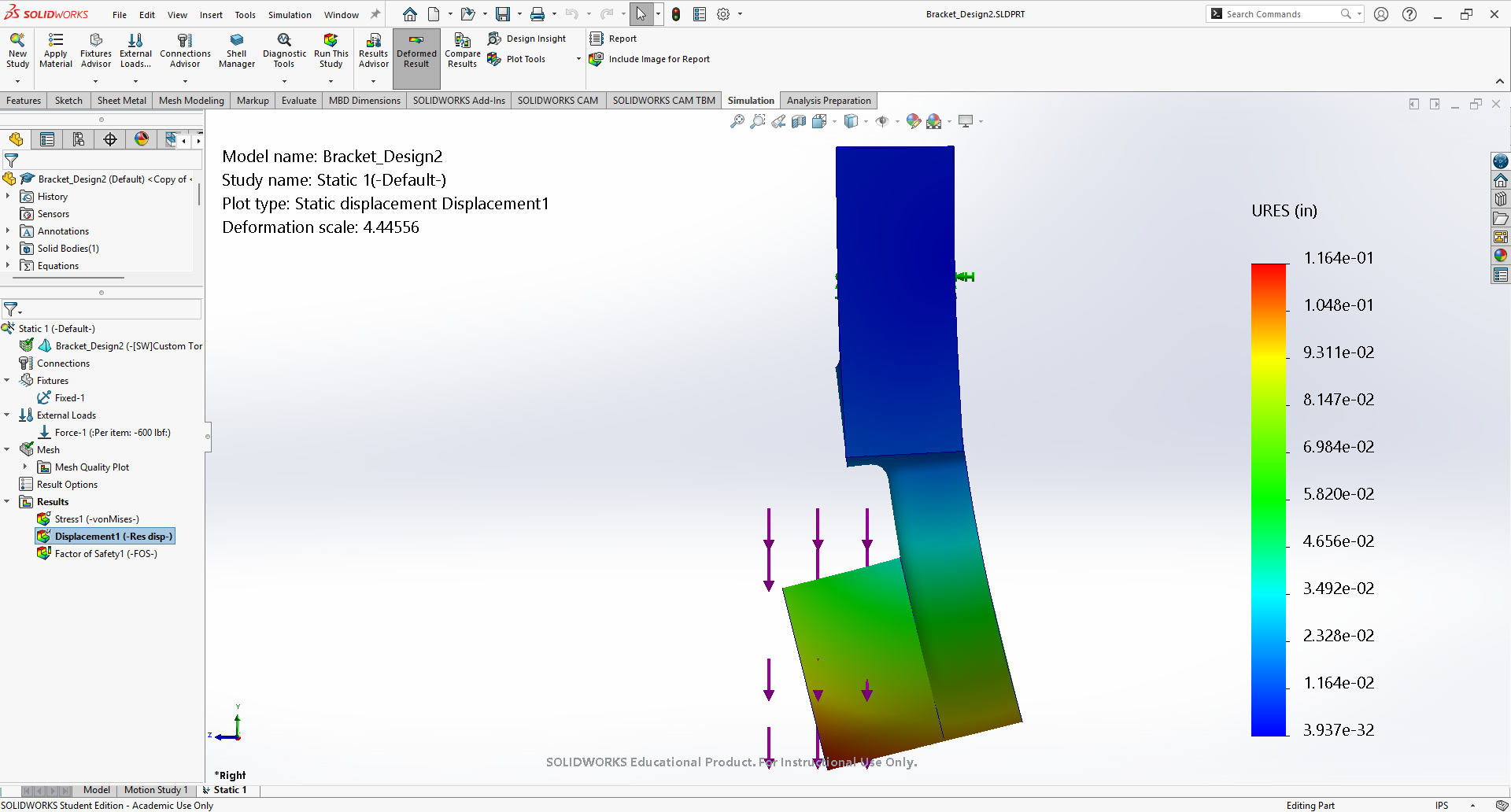
35. Side View of Deflection (Scale:4.44556) - Design 2
By taking a closer look, I noticed that the maximum stress location did not change compared to the original design. This meant that my round feature was likely too small and I would need to increase the size. For the deflection, it became obvious that Section A and B were deflecting the most. My initial thought to reduce the deflection was then to increase the depth of Section B. There seemed to be no noticeable change for my increase to Section A's diameter, so I also reverted back to the original diameter. There was also a small stress concentration forming on the inside edge of Section D, so I added that edge to the round.
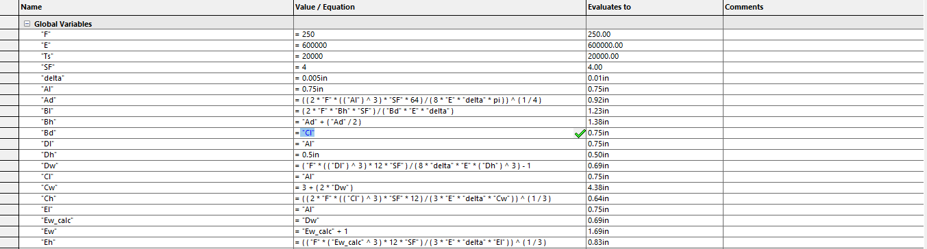
35. Increasing Section B depth to match Section C
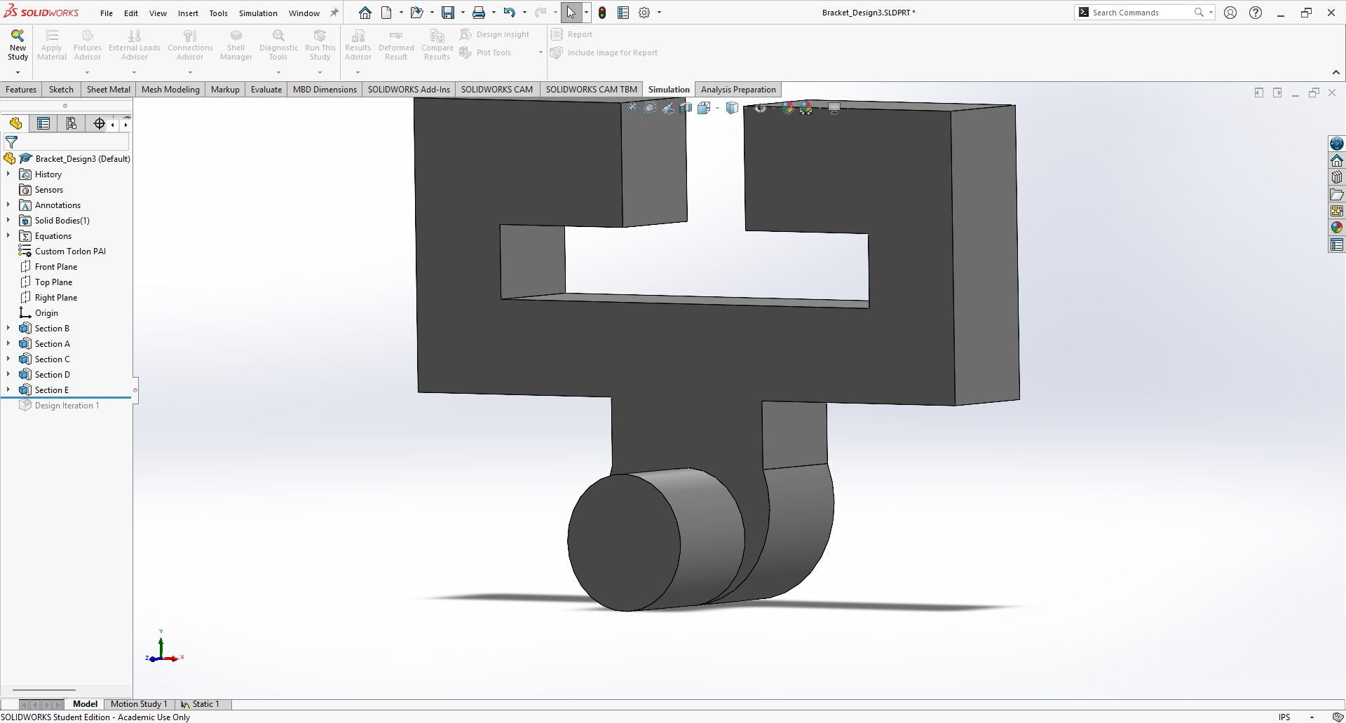
36. New Section B depth
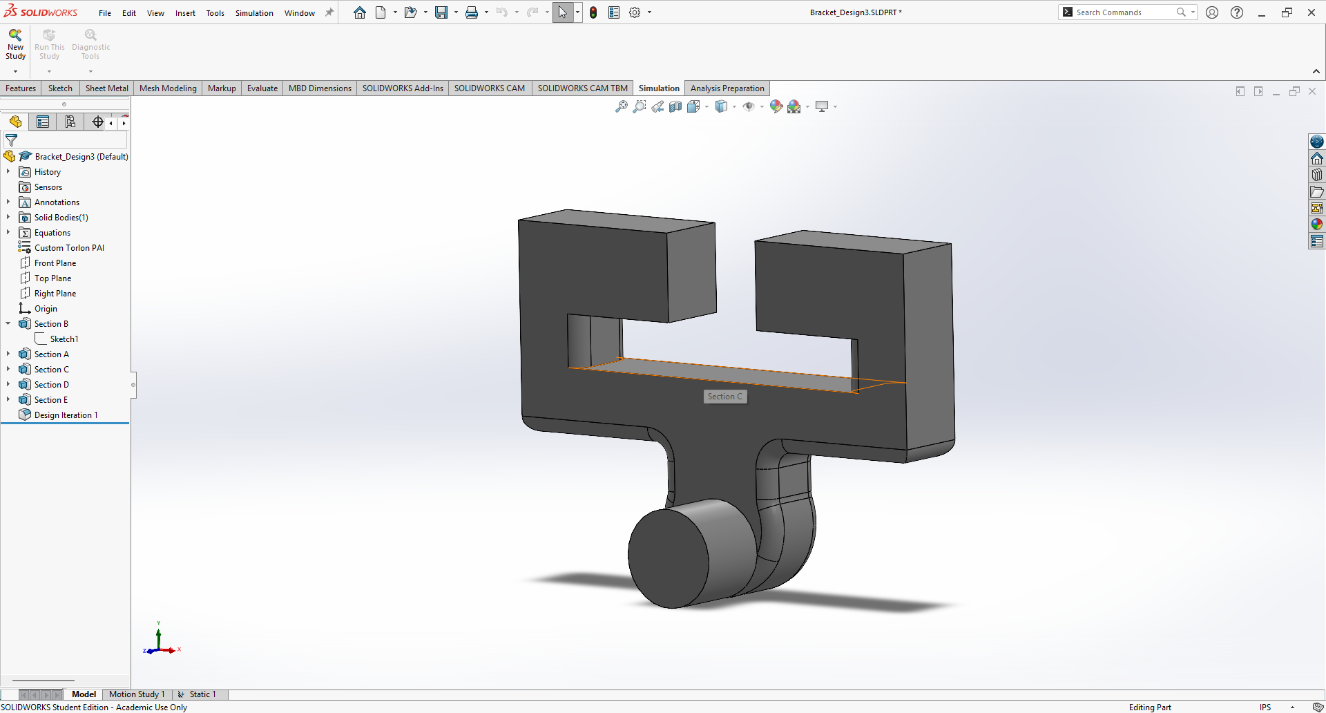
37. Additional Rounded Edges
I was unsure as to if these changes would be enough to reduce the deflection down to 0.005 inches, but I felt hopeful that it was reduce my max stress and increase my minimum safety factor. Before testing too much, I ran a default mesh size simulation and checked just the deflection to see if my design was closer to the target.
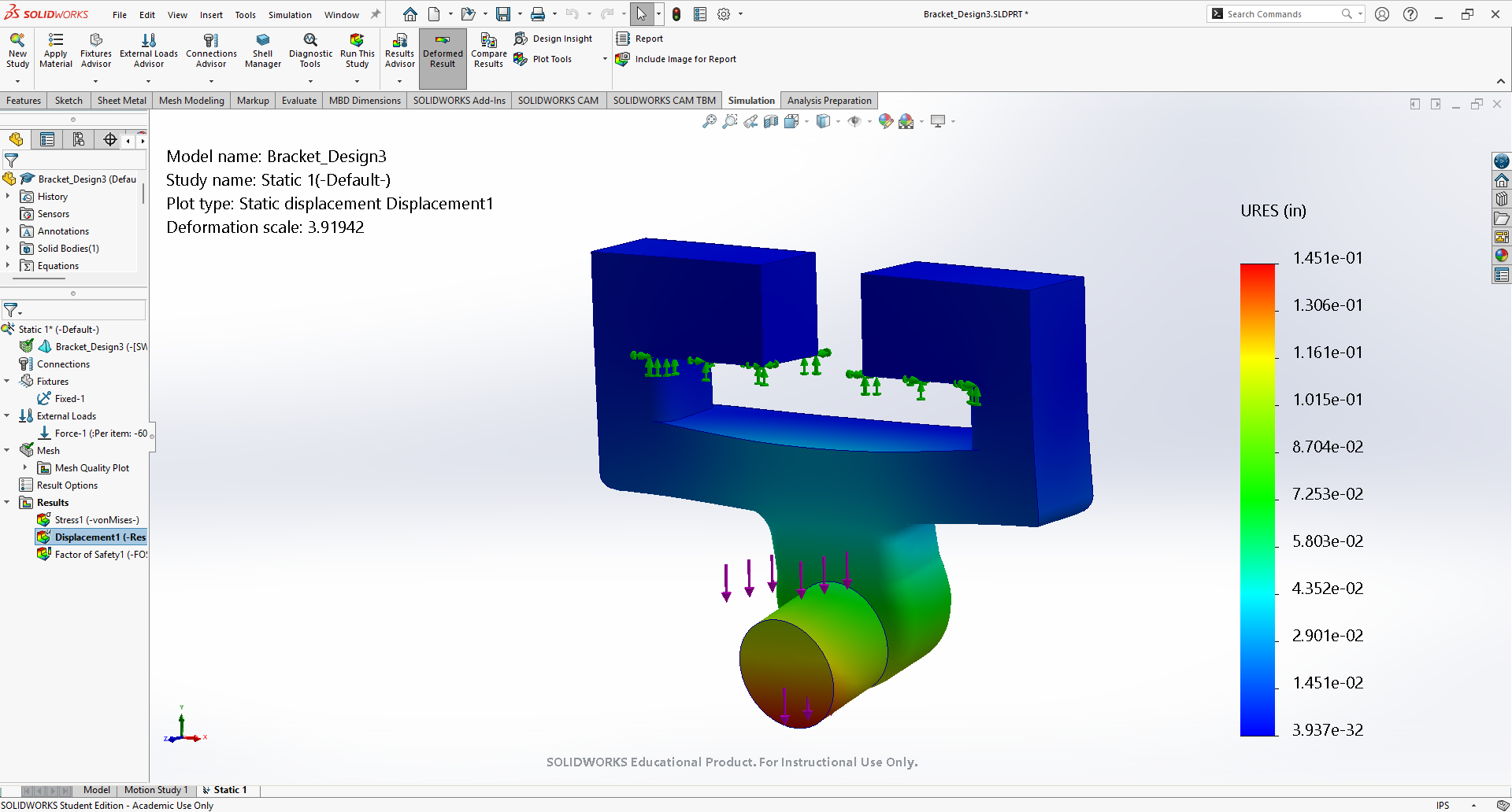
38. Deflection for initial Design 3 Changes
As you can see in image #38, the max deflection was actually increasing! This frustrated me and caused me to make various small tweaks and edits to essentially the same geometry, but nothing was working. I decided that I should take a quick break to eat, think about the design, and then come back to it with fresh eyes. When I came back, I remembered looking at some of the TA's portfolios for Assignments 5 to see how they formatted their information and to get inspiration for how to model and calculate some of the bracket sections. I had noticed at the time, that their bracket models included a second Section B that connected to the front of the part. I believe this design feature was already included for their assignment and calculations, but ours did not. It seemed so simple then that I could reduce the deflection at the tip of Section A by fixing it to the front face of the bracket. With that realization, I went back into my model to add a front plate that would reduce the maximum deflection.
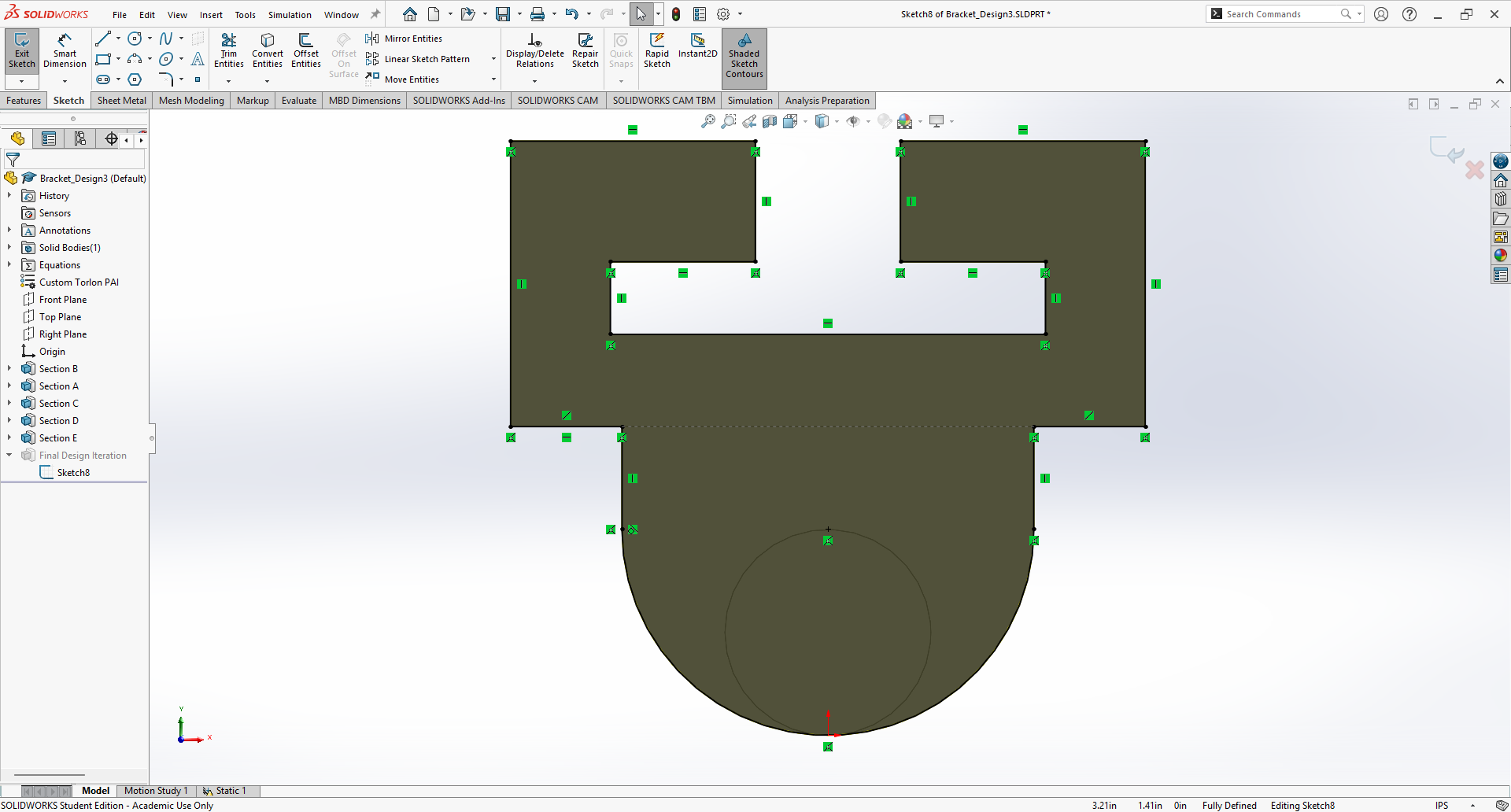
39. Creating the Silhouette Sketch of the Cross Section
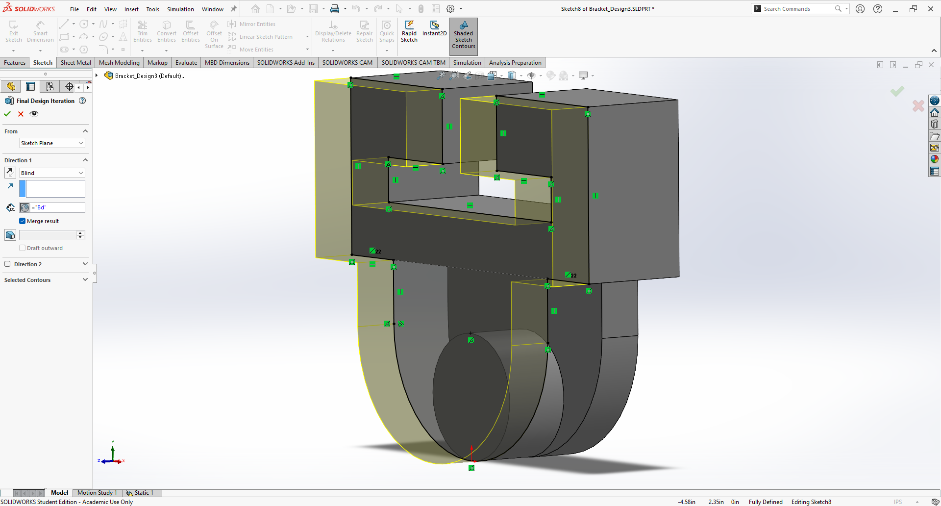
40. Extrusion of the Section
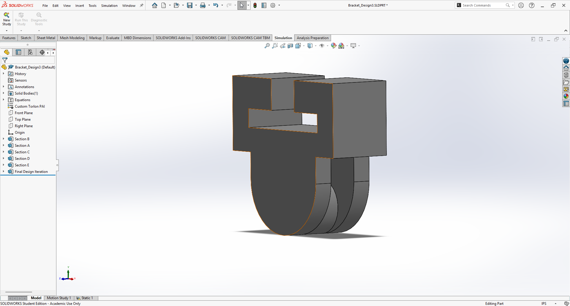
41. Design 3
I intentionally left off the rounds, although they may have been helpful for further optimization. At this point, I felt it would not be crucial to re-include them. The additional support material should be more than enough to reduce the stress concentrations to be within a reasonable limit. At this point, I was ready to do my last full FEA analysis.
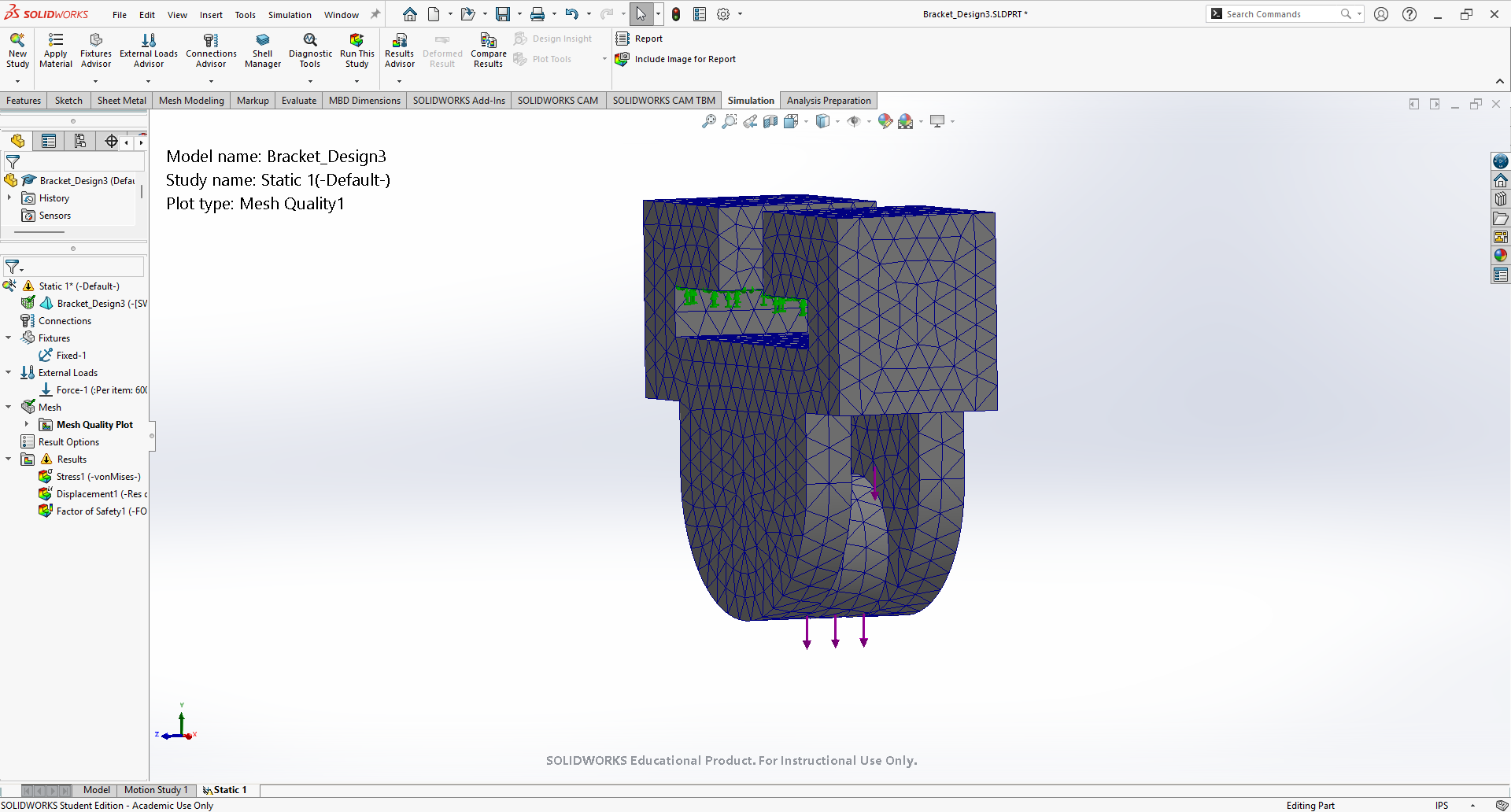
42. Design 3 - Mesh 1
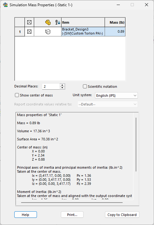
43. Design 3 - Mesh 1 - Mass
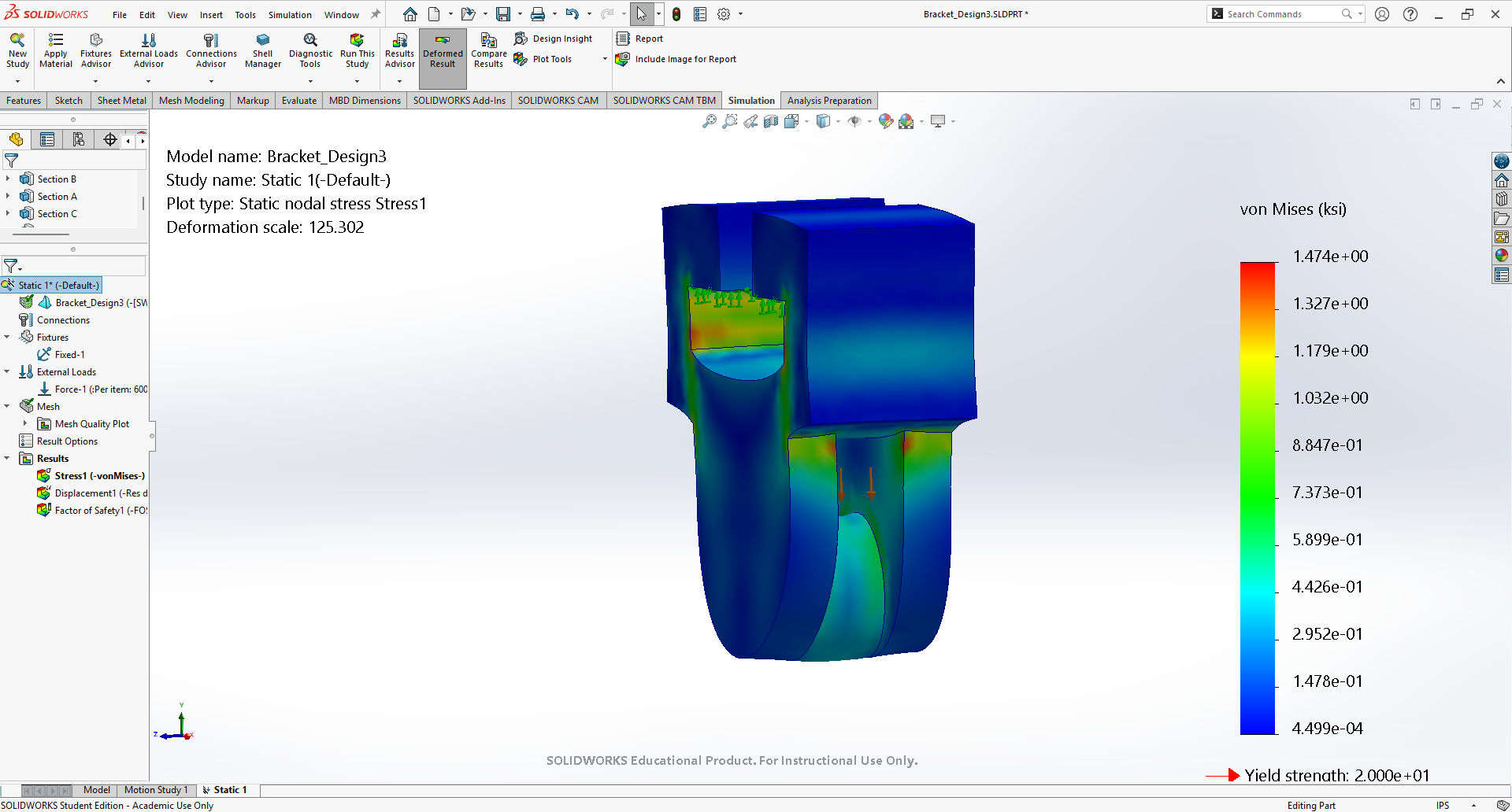
44. Design 3 - Mesh 1 - Stress
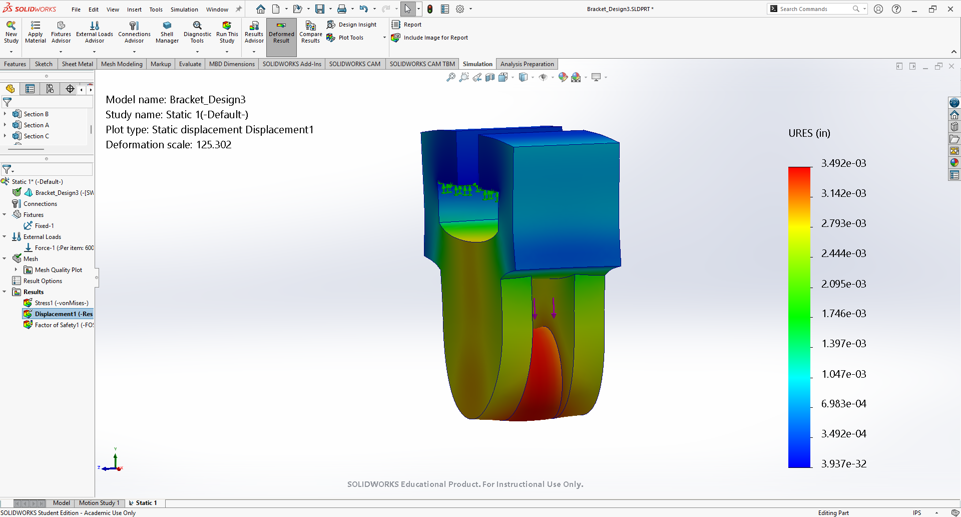
45. Design 3 - Mesh 1 - Deflection
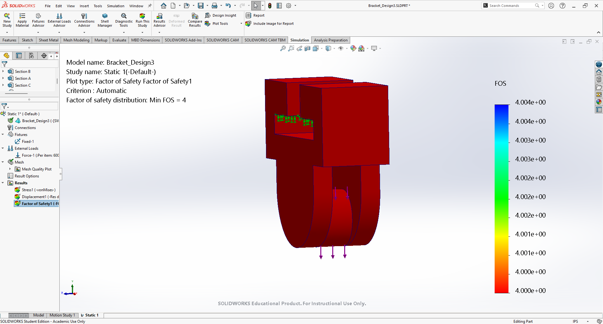
46. Design 3 - Mesh 1 - Factor of Safety
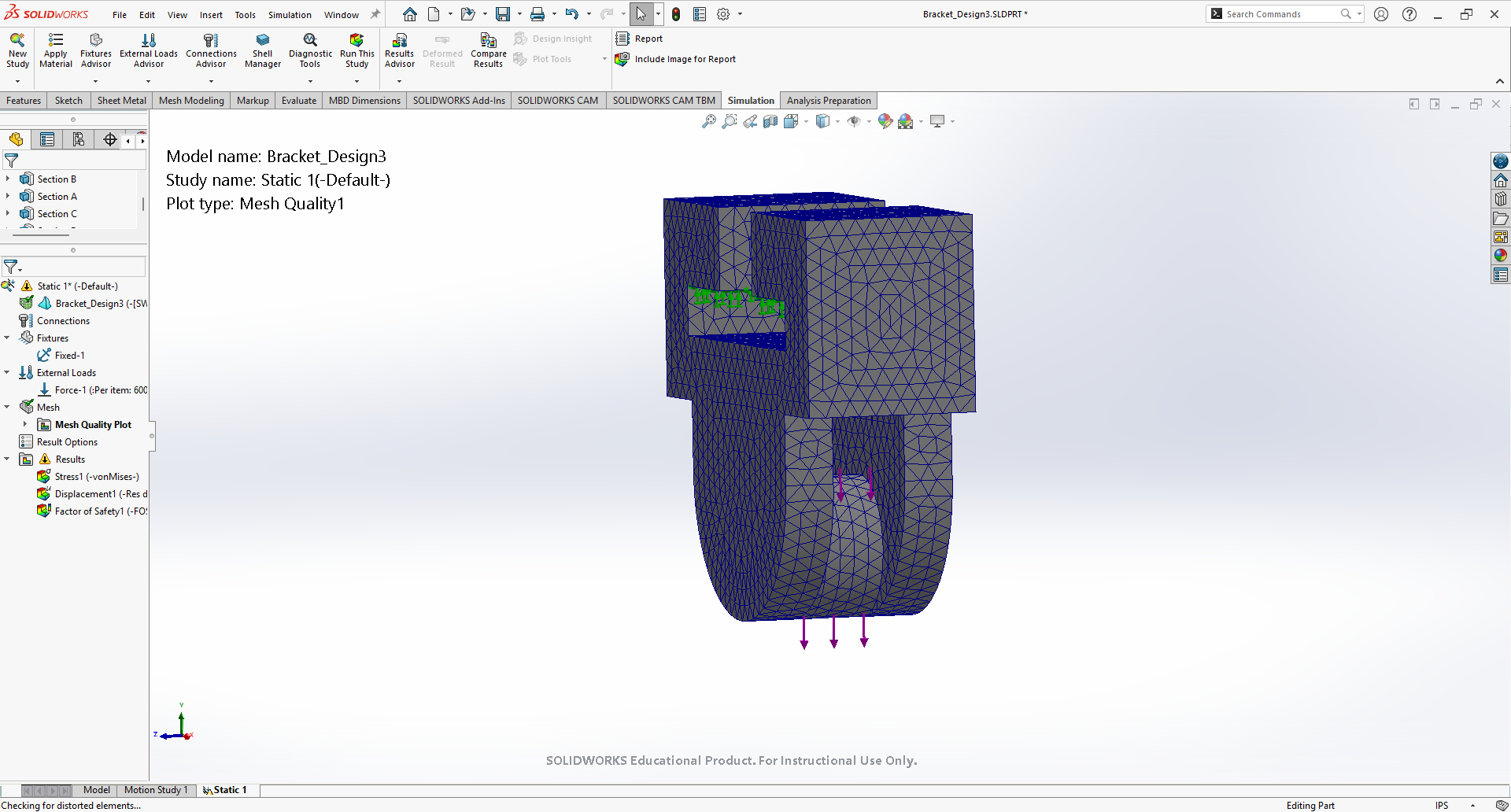
47. Design 3 - Mesh 3
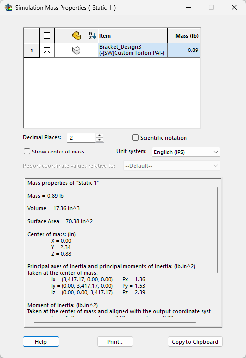
48. Design 3 - Mesh 3 - Mass
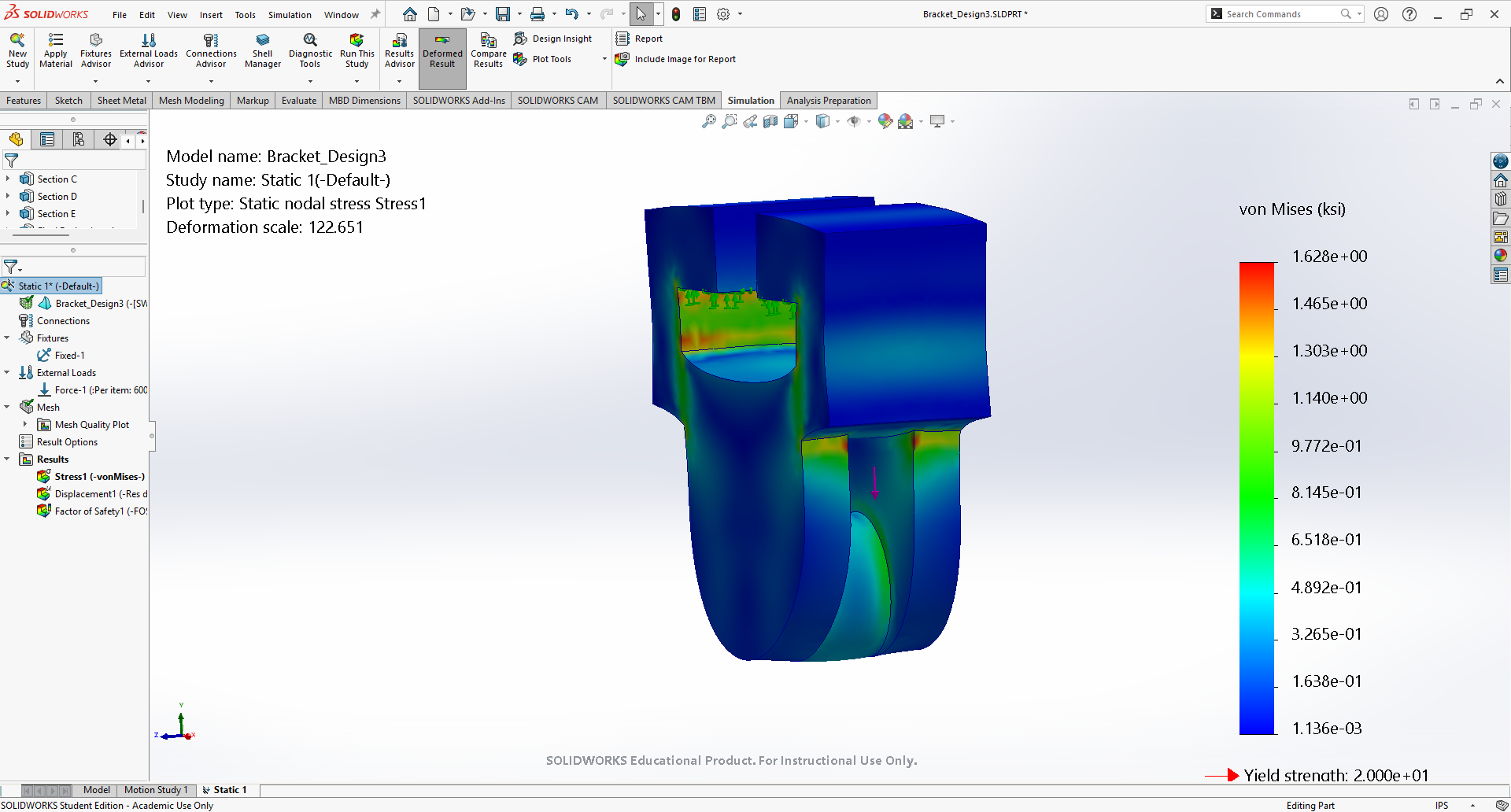
49. Design 3 - Mesh 3 - Stress
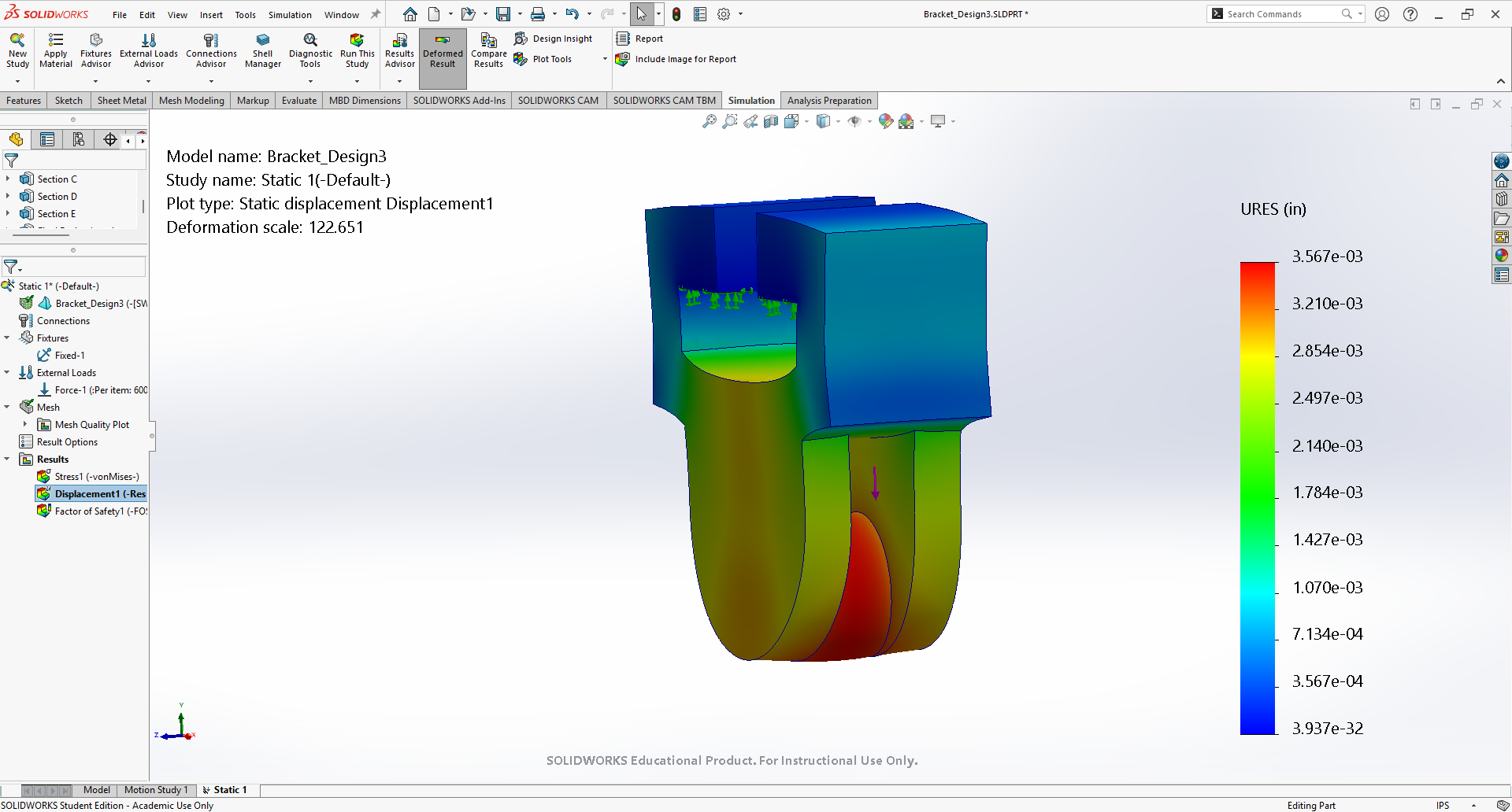
50. Design 3 - Mesh 3 - Deflection
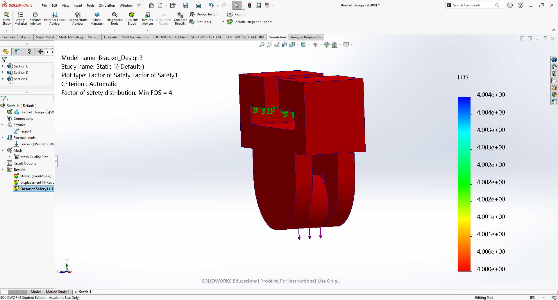
51. Design 3 - Mesh 3 - Factor of Safety
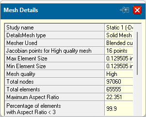
52. Design 3 - Mesh 3 - Number of Elements
I was very happy to see that I had reduced my maximum deflection drastically, enough that it was less than the target of 0.005 inches. When calculating my convergence for the default and slightly finer mesh sizes, I got a percent difference for stress that was larger than 7%. This could be due to me removing the rounds and allowing a stress concentration to sneak in and cause some minor variance in the FEA calculations. I needed to run a third mesh so that I could test if the trend continues between the finer mesh and what I picked to be the most fine mesh size. Unfortunately, the stress again was over the 7% limit, but since the rest of the values were the same, I had enough information to infer that the max stress was within my final target limits since stress concentrations at fine mesh sizes have a tendency to become divergent when everything else is convergent. With this final design iteration, I was able to update the table one last time.
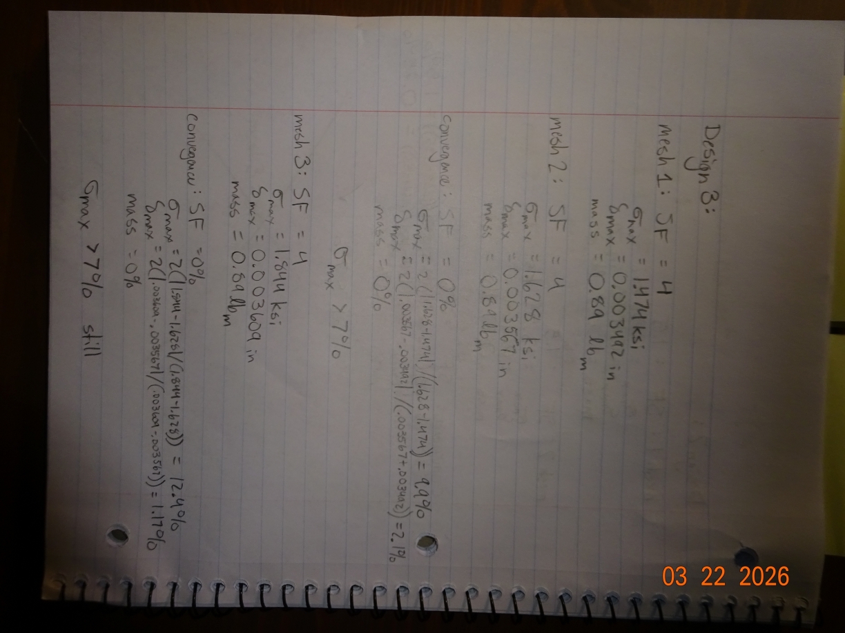
| Design 1 | Design 2 | Design 3 | |
| Max Stress and Location | 12.8 ksi at the top corners of Section B as they connect to Section C | 13.55 ksi at the top corners of Section B as they connect to Section C | 1.844 ksi at the top corners of Section B as they connect to Section C and the bottom inside edge between Sections C and D |
| Max Deflection and Location | 0.1142 inches at bottom of Section A | 0.1164 inches at bottom of Section A | 0.003609 inches in the middle of Section A |
| Mass | 0.70 lb | 0.37 lb | 0.89 lb |
| Safety Factor | 1.6 | 1.5 | 4 |
| Number of Elements | 9,079 | 25,977 | 65,555 |
Lessons Learned
The last design iteration showed me the importance of thinking big when it comes to design changes. For my second iteration, I was too tame and while my changes were not wrong, they did not make enough of a difference at the root of the problem. I also learned that it does not hurt to take a break and come back with a fresh perspective or to take inspiration from other existing designs. It also does not hurt to try out different solutions, even if they don't make it to the final design. When it comes to FEA, this assignment helped me better understand the basic principles behind how it works, why it works, and why its used so commonly. It solves complex modeling equations and is able to give really
nice visuals for what is happening to the model under its defined state. I also was able to better understand what mesh sizes were and why its important for FEA calculations, since up until now I always thought of mesh sizes for 3D models as being a visual accuracy thing. In Finite Element Analysis, it relates to the "accuracy" of the calculations to an extent. For prototyping, this gives a much better idea to how the part might perform without having to spend much of anything on multiple design iterations. In conclusion, FEA is an extremely helpful tool to have alongside the great technology of CAD programs when designing models.
I would say that in total, I spent around 8.5 hours in total on this assignment. About 5 of those hours were spent in SolidWorks running the FEA and making design changes, and the other 3.5 were spent on the hand calculations and portfolio creation.
- Design 1 with Simulation .zip, download here
- Design 2 with Simulation .zip, download here
- Design 3 with Simulation .zip, download here
- Hand Calculations .pdf, download here