
Design with Basic Stresses
This assignment involves students generating a geometric design for a truss that will need to support a load with proper safety factors.
Several objectives were given in the assignment description:
- Design a lightweight planar truss using A500 steel or an alternative material.
- Create free body diagrams (FBDs) for joints and critical pins.
- Calculate the required cross-sectional area of truss elements with a safety factor.
- Determine pin sizes based on shear forces with a safety factor.
- Solve equations symbolically and numerically for both truss and pin design.
- Estimate the total weight of the truss and pins.
- Create a CAD model with accurate dimensions and connections.
- Compare CAD weight predictions with hand calculations.
- Document key engineering lessons learned from the process.
Students were also asked to document every step no matter how small and to share all successes and/or failures during the process.
Below are the design constraints given for this assignment.
"Design a light weight planar truss using A500 structural steel (Some software will not have this material, use another type of steel). There are four steps outlined below. Steps 1 through 2 require FBDs as well as calculations to determine the design. The third step requires a CAD model and verification of the analytical calculations in the previous steps.
- Design constraints are shown in Figure #1. (See Appendix for deeper explanation).
- The cross sectional area of each element is to be identical.
- The pins are to be identical to each other and each element is to have the same cross-sectional geometry.
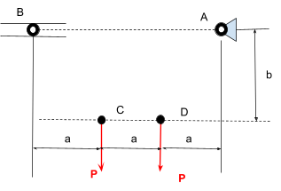
Figure #1.) The force and geometric constraints of the truss design problem.
P = 15 kN. a = .4 m, b = .3 m. Point A is a pin and point B is a roller."
My Design and Process
Designing the Overall Truss Geometry
I began my process by simply writing down everything that was given within the assignment description.
Once I had everything copied, I went straight to sketching rough truss designs that would fit our constraints. I tried about three different sketches before I ended up settling on one to continue working with.
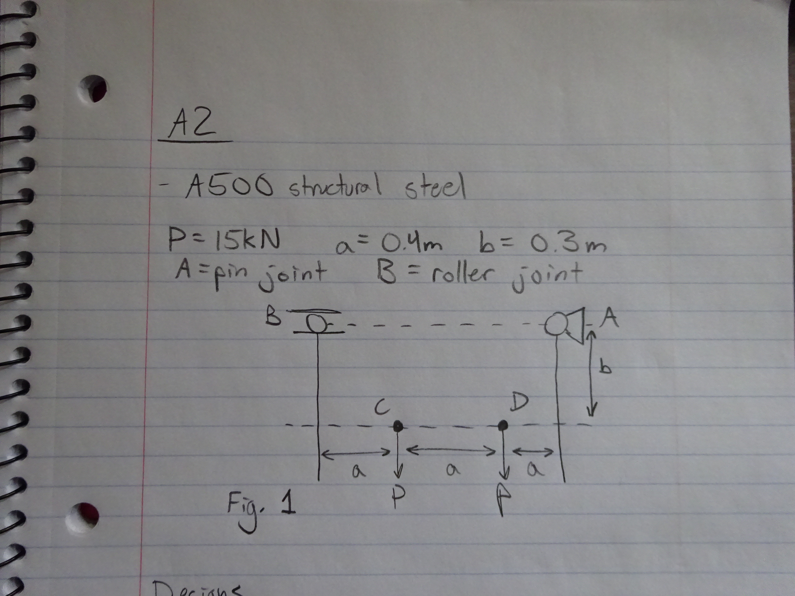
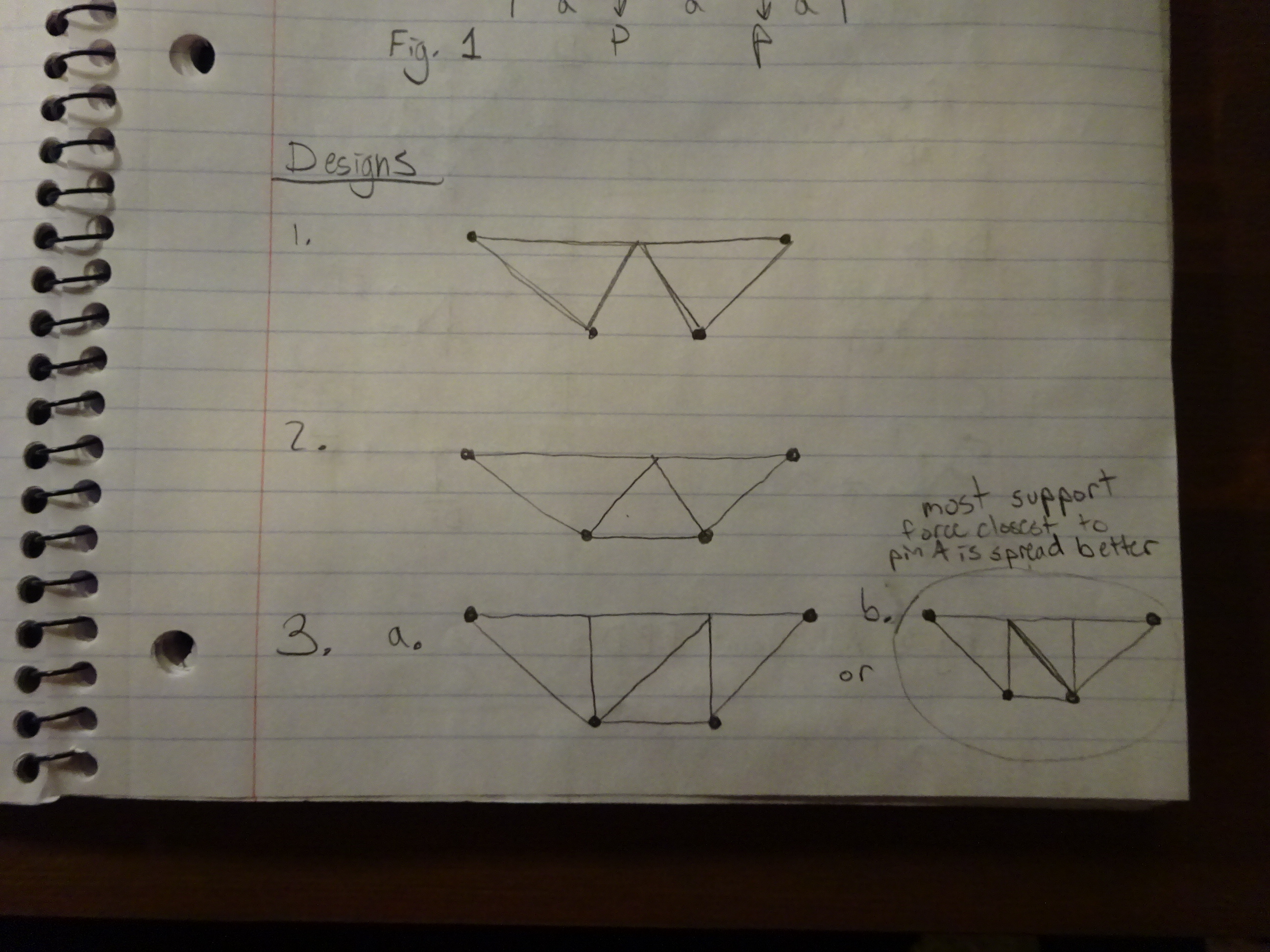
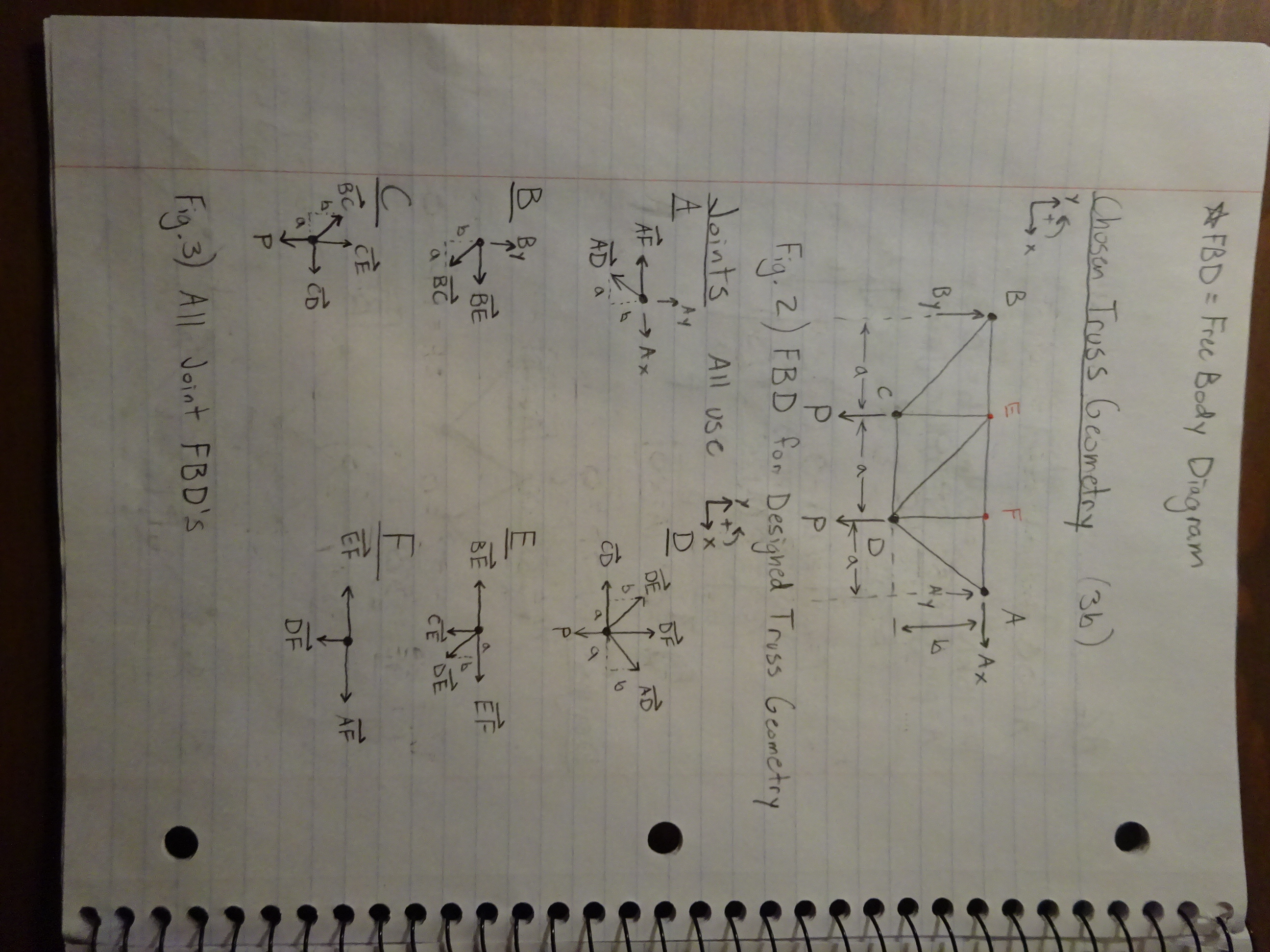
As you can see in the image on the right, I chose drawing 3b from my sketches. I liked this design since it looked the most supported near the pin joint A. I knew that this many members and joints would be time consuming to solve, but I hoped that the work would pay off with a lower maximum internal force. Unfortunately, I could not know this for sure until I started working it through, so I drew my free body diagram (FBD). Figure 2 in the image below is my initially worked design of the truss geometry. Figure 3 in the image is the individual FBD's at each joint.
The next step in the design process was solving all members for their internal forces. I had chosen a design with 9 members, so this took quite a while. It also took me a substantially longer time than necessary due to repeated errors during my symbolic calculations. The image below shows my first main error which took me about an hour to realize, since I forgot to include a member's force in the second equilibrium equation of the first joint I analyzed.
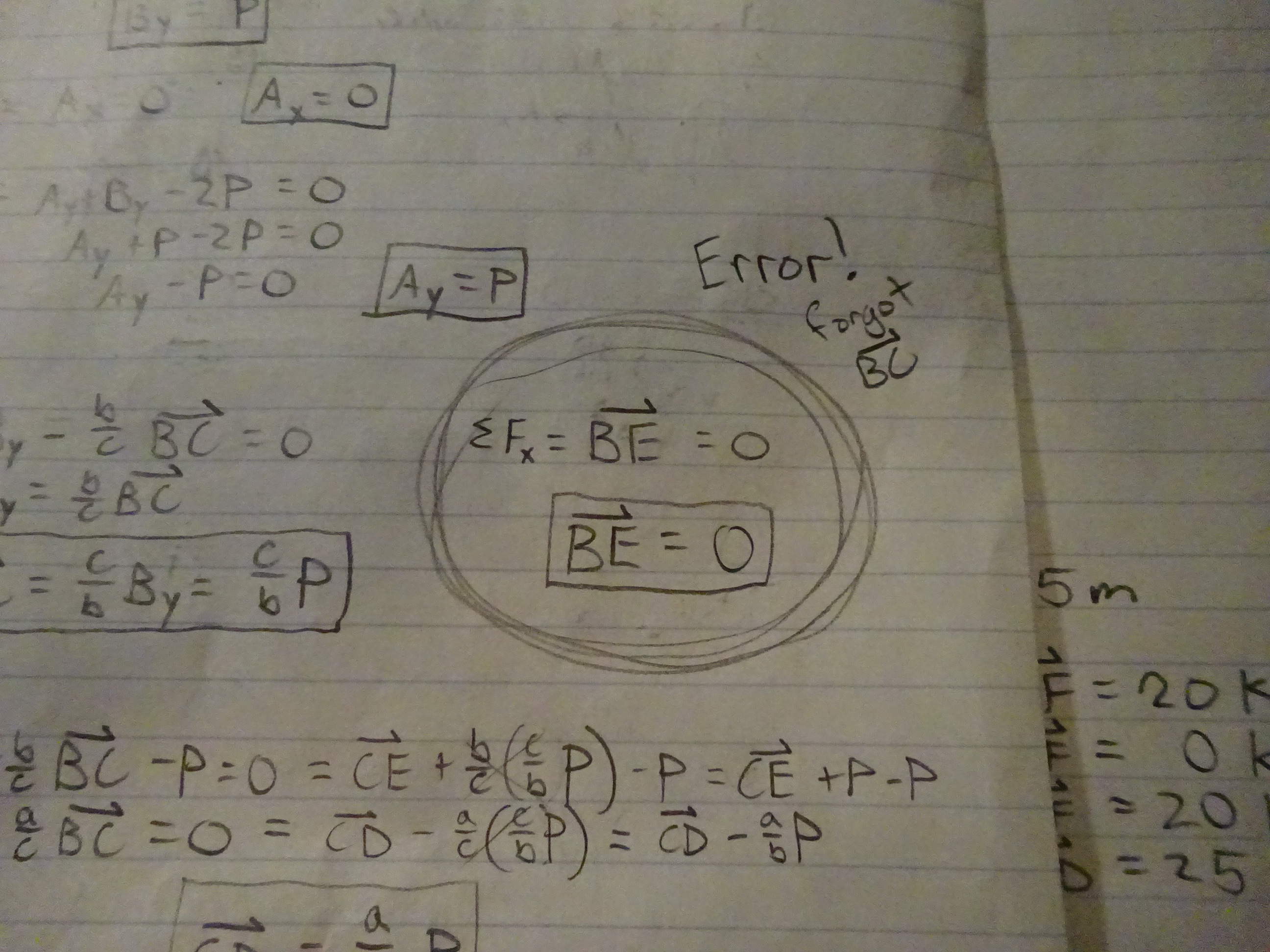
This was not the first and surely not the last mistake that I made during my calculations and CAD modeling process. This first big error added at least an hour to the time it took to complete this project, so I was sure to minimize distractions and be more attentive to each step I took. Having gone much more carefully over the steps and equilibrium equations, I finally had my symbolic answers to the internal forces. This meant that each member was solved in relation to the given "P" force and the given lengths of "a" and "b." All my work is shown in the images below. Figure 4 is a depiction of the truss with the internal forces near the corresponding member.
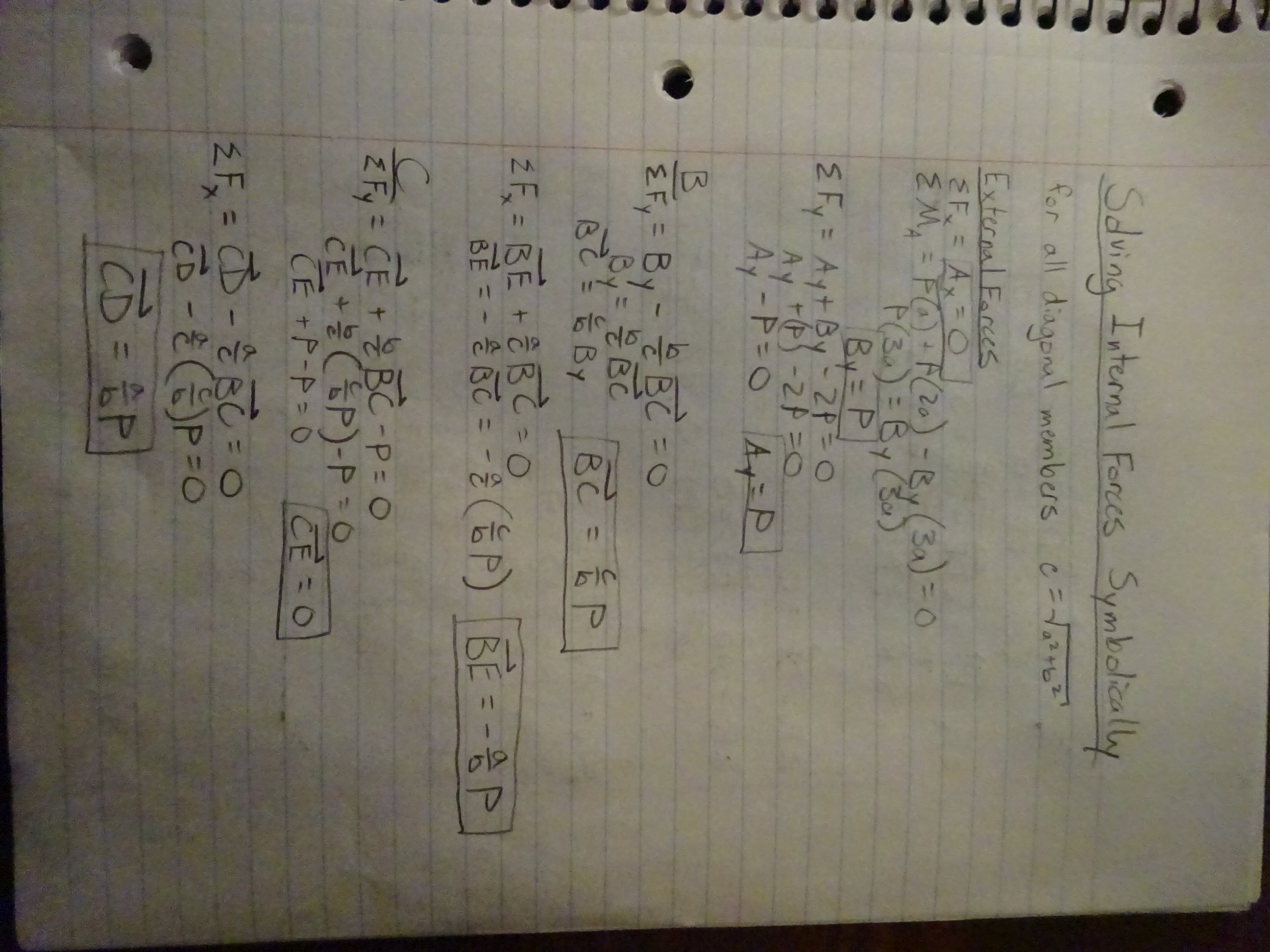
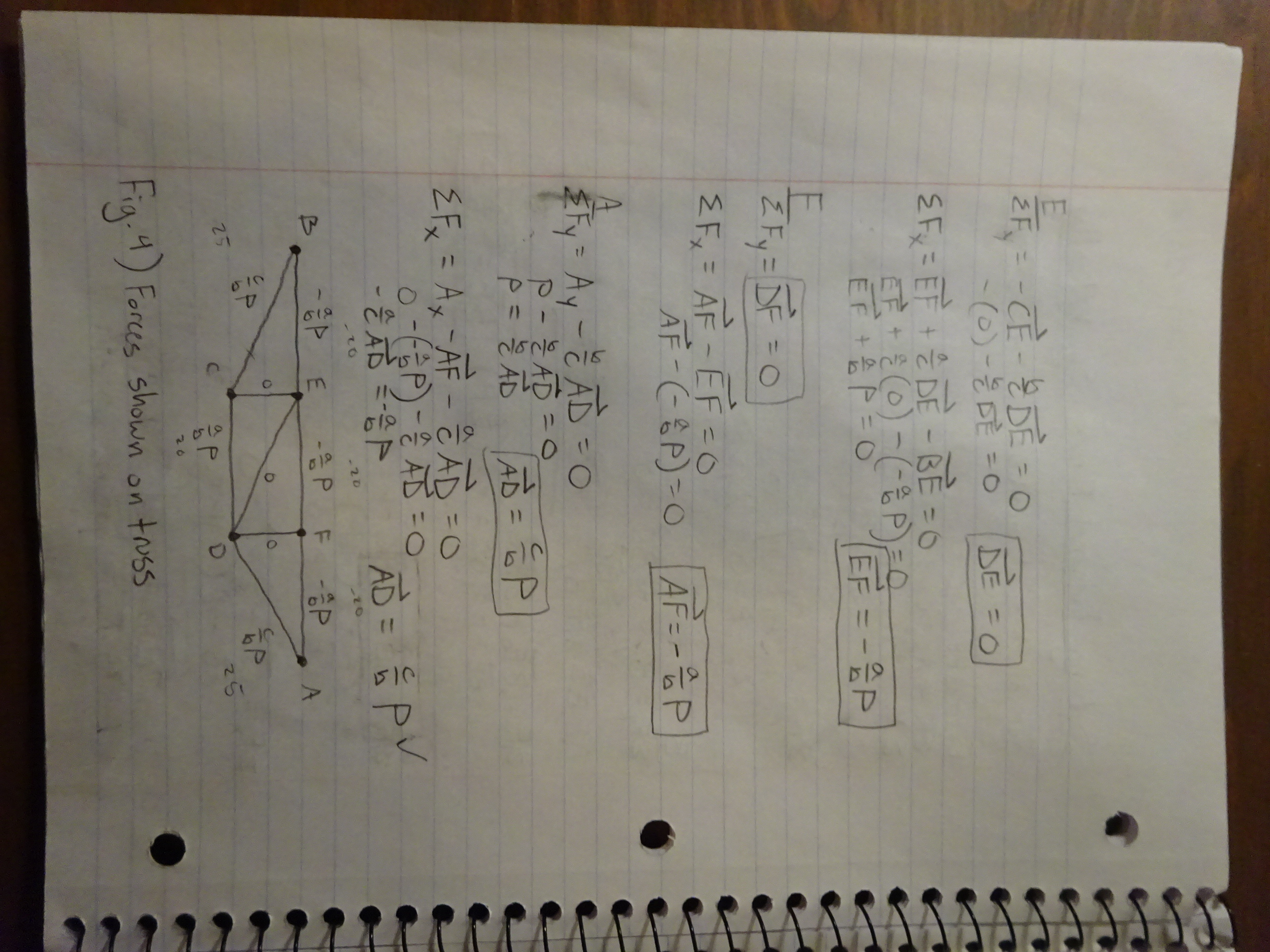
For easier viewing and calculations, I followed this section with a clean page listing all symbolically solved members and relisting the variables as given in the assignment description. I then plugged in all values to get final numeric answers. To check my work, I went back through each equilibrium problem plugging in all values as given/calculated and made sure they all balanced to a net of zero Newtons.
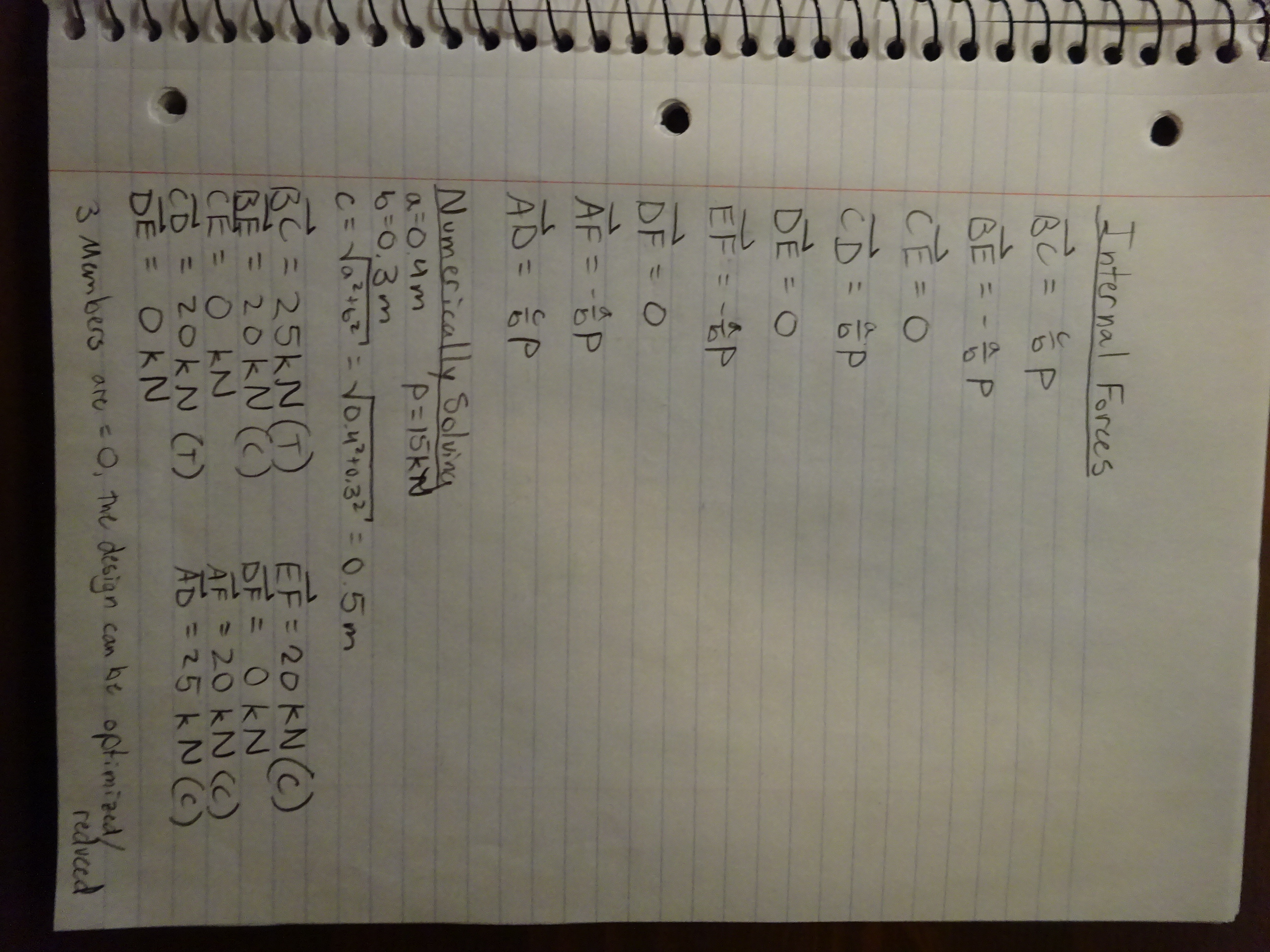
On the bottom of the last page, I added a note referencing the fact that three of the members in the middle of the truss had zero internal forces acting in them. To me, this meant that my truss design was not well optimized, and instead of being extra supportive, it was overly complex for the given assignment constraints. This sent me back to my sketches to see if another option would be less complex and possibly even be symmetric to reduce the amount of calculations necessary for the truss. Eventually, I settled on the sketch #2, since it was the simplest design I could think of without losing the member between pins B and C. I felt this member was necessary compared to sketch #1 since without it the truss would be joined in the middle only by a pin. The triangle's fundamental geometry is what makes trusses so strong and keeps them stable, so without it my truss could work in theory but still not fit the description of a geometric truss. From here I followed my original steps of drawing all FBD's for the truss and joints.
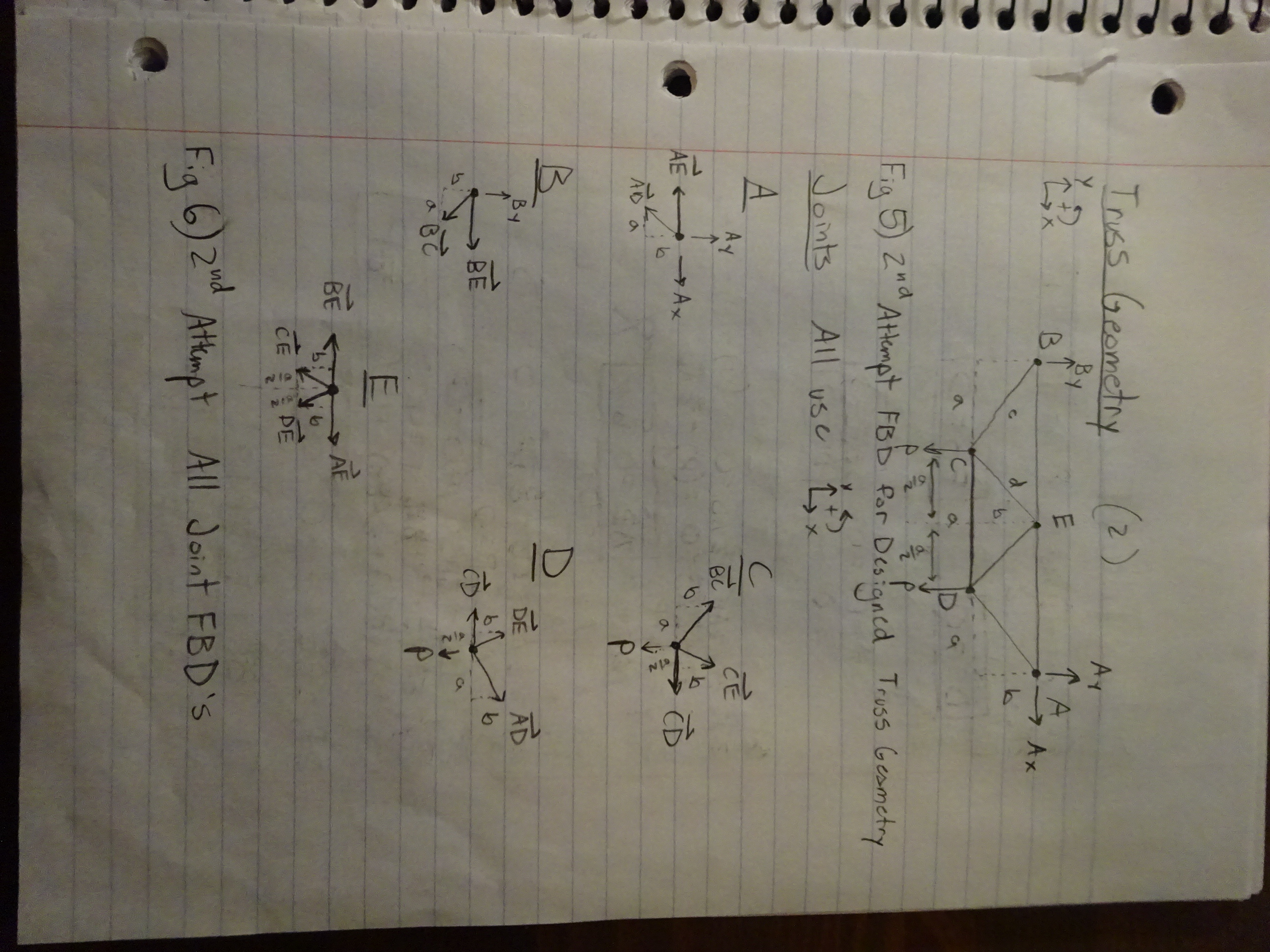
The new design had only five pins and seven members, while also having the perks of a symmetric design. Solving the members symbolically was a little more complex, but only half of the truss had to be solved to know all internal forces. The work is shown in the image below along with Figure 7 which shows the symmetric relationships on the truss.
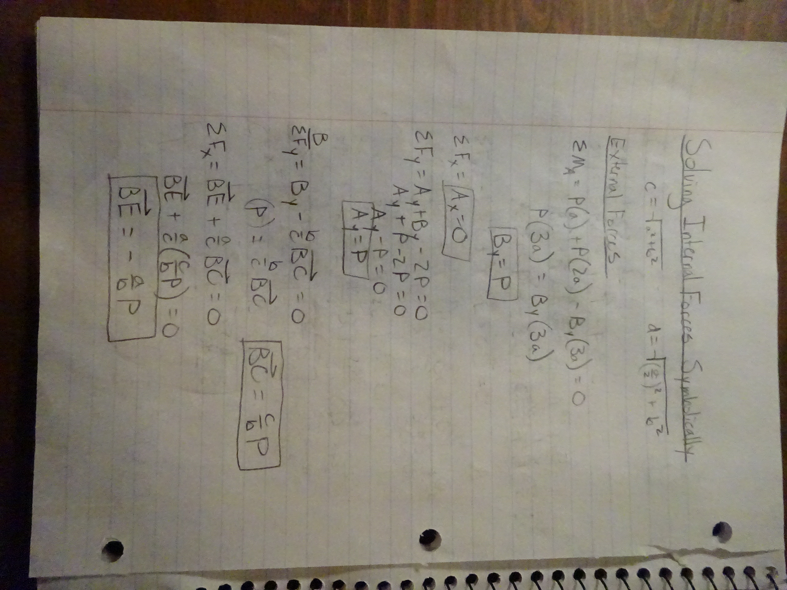
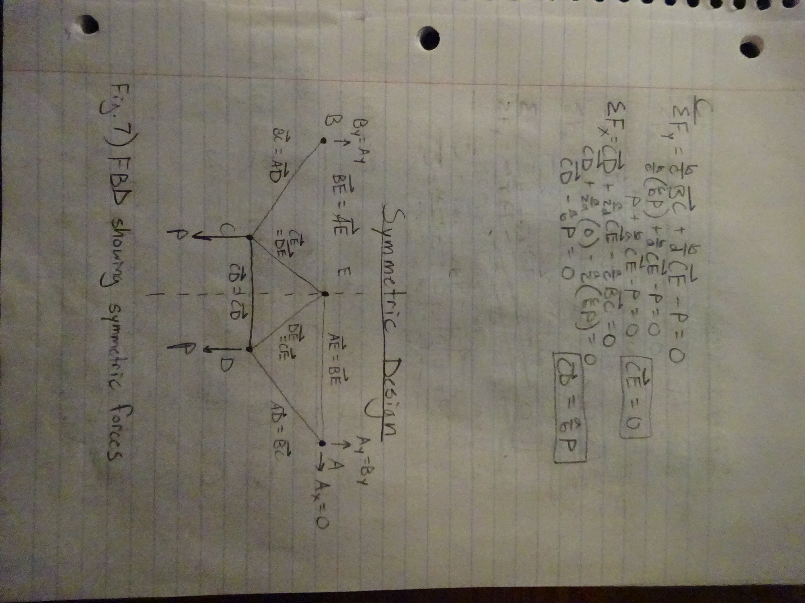
Again, for simplicity and clarity, I copied each members' symbolic solution onto a new page, restated all givens and calculated lengths, and then solved for the numeric solutions. In the image below you can see that there are now only two members with zero internal force, and the maximum force of the truss stayed the same compared to my previous attempt at the truss geometry. Once I had my numerical answers, I also went back through each of the equilibrium equations to make sure they balanced to a net of zero force. This way I could be sure that my calculations and final values were correct.
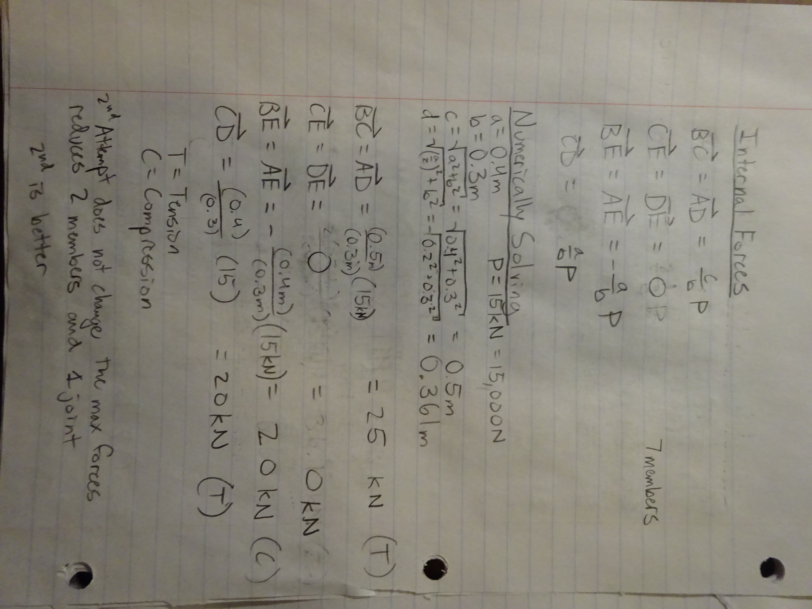
Now that I had two solved trusses, I had to decide which one to complete the assignment with. I still appreciated the first design, but the symmetry and lower number of members from the second design was much more appealing to work with. I stuck with the second truss geometry and continued the assignment.
The next step in the design process was determining the minimum cross-section needed for the members. To do this, students had to research the material to find the yield strength. I knew that I would be using SolidWorks for the CAD portion of this assignment, so I went into their material list to see if I could find the A500 structural steel given in the assignment description. SolidWorks did not have this specific steel, so I researched what other steels were similar for substitution and also fit with SolidWorks' library of materials. One article I found was from MWalloys and can be found at this link. The article goes through the materials of A36 versus A500 steel. The parts I found important were the chemical materials, manufacturing process, and yield strength. The article outlines how both steels have very similar elements in them, although A500 has higher percent of Manganese and Silicon, which make its strength a fair bit higher than A36. Both steels are fairly common, and they can be manufactured in bars and many shapes. Lastly, the yield strength was most important for this assignment. A36 steel does have a substantially lower yield strength, but since the assignment preferred a material of higher strength, I decided it would be okay to use a steel with a slightly lower yield strength. This means that if my designed truss was to be created with the A500 steel instead, there is a better chance that the cross-sectional area I calculate would still be satisfactory for the stronger material.
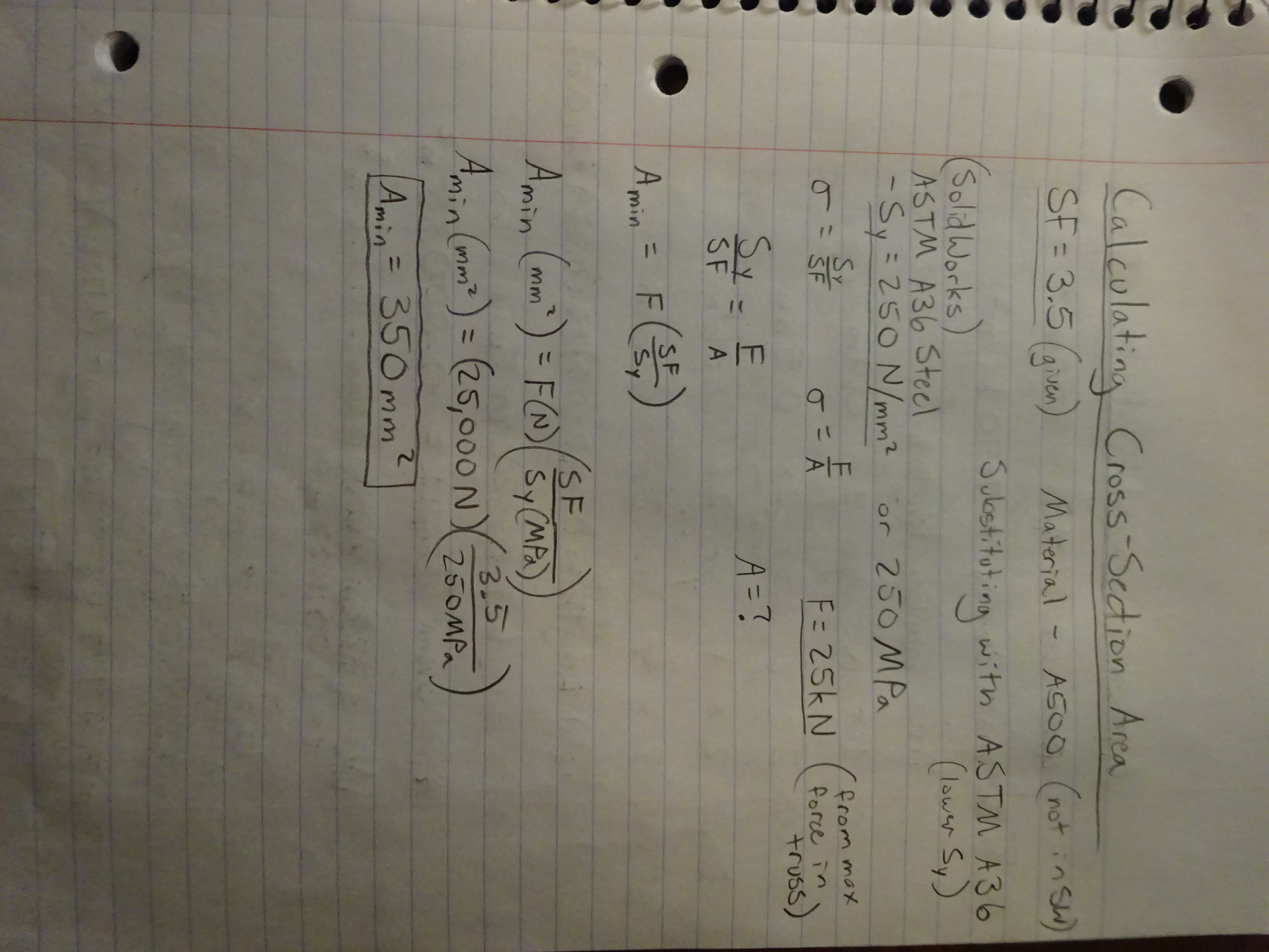
After settling on A36 steel as my substitute material, I went back into SolidWorks to find the yield strength. I used this yield strength along with the given safety factor of 3.5 to get my maximum average normal stress in the truss member. I then substituted the largest internal force into the normal stress equation to solve for the minimum area of the members. The work for this step can be seen in the following image.
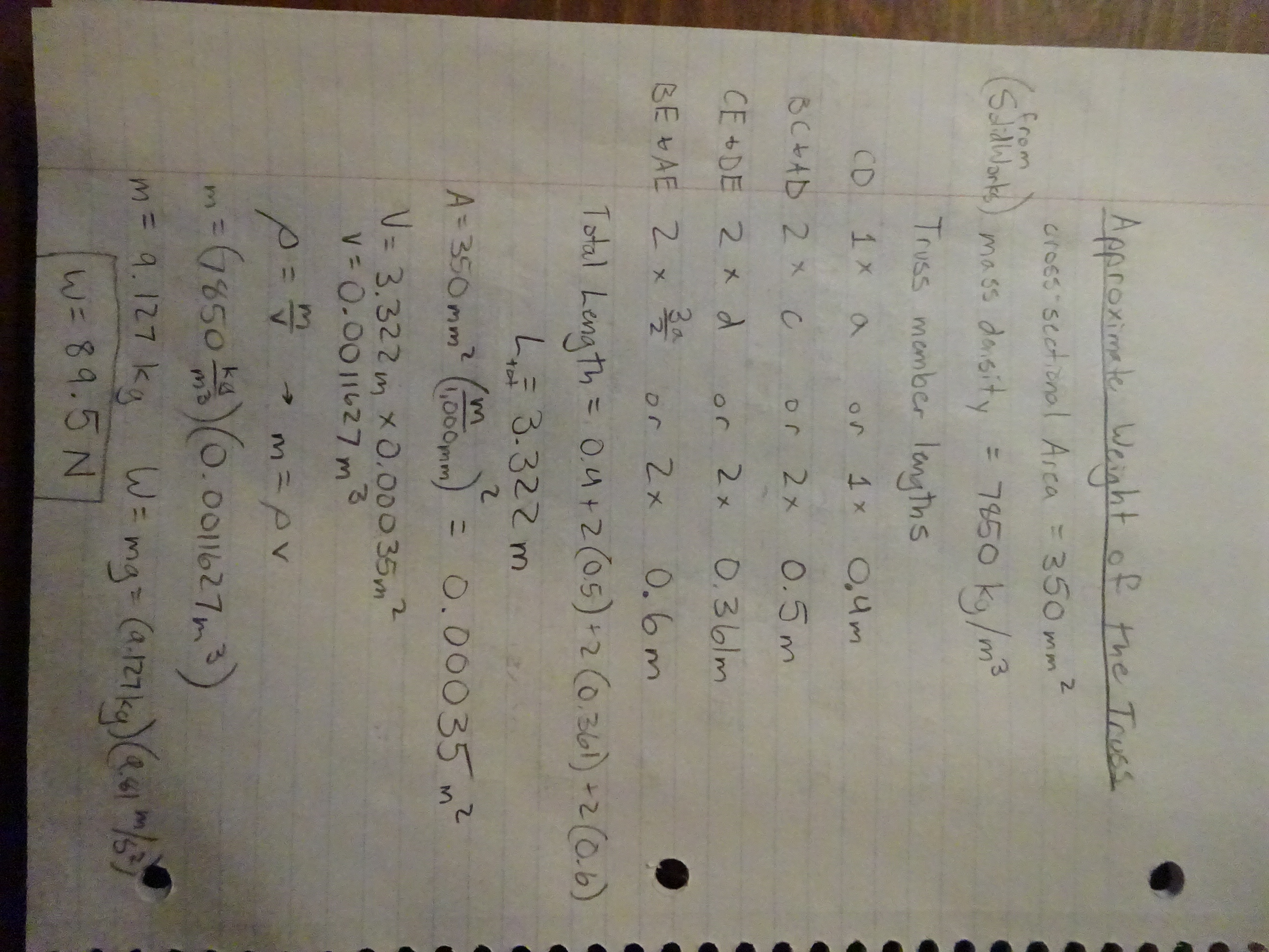
With the minimum cross-section, the approximate weight of the truss could be calculated using the total length of all members to get the volume of the material. I used the density of A36 steel as given in SolidWorks, and found the approximate weight to be 89.5 Newtons. The work to find this value can be followed in the image below. Later, this value will be compared to the approximate weight of my CAD model.
Pin Calculations
Now that the truss geometry is defined, the pins needed to be designed to match the geometry along with some given constraints. The shear yield strength and density were given in IPS units, and the required safety factor was 4. The material quoted was hardened tool steel, but since SolidWorks did not have these exact values, I had to substitute with regular tool steel with approximate values.
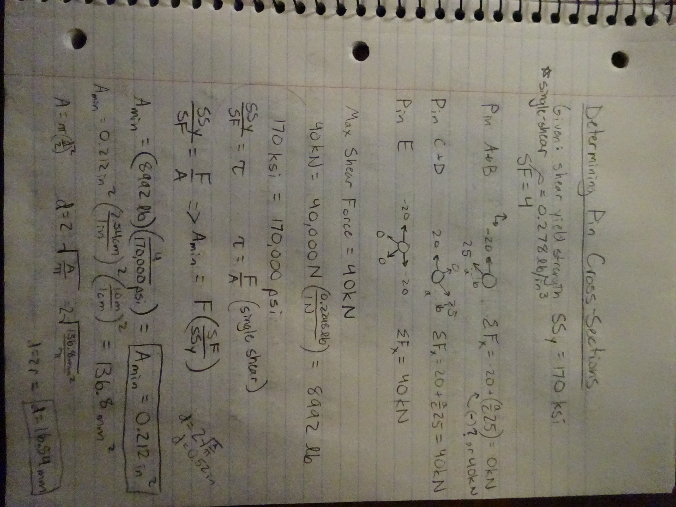
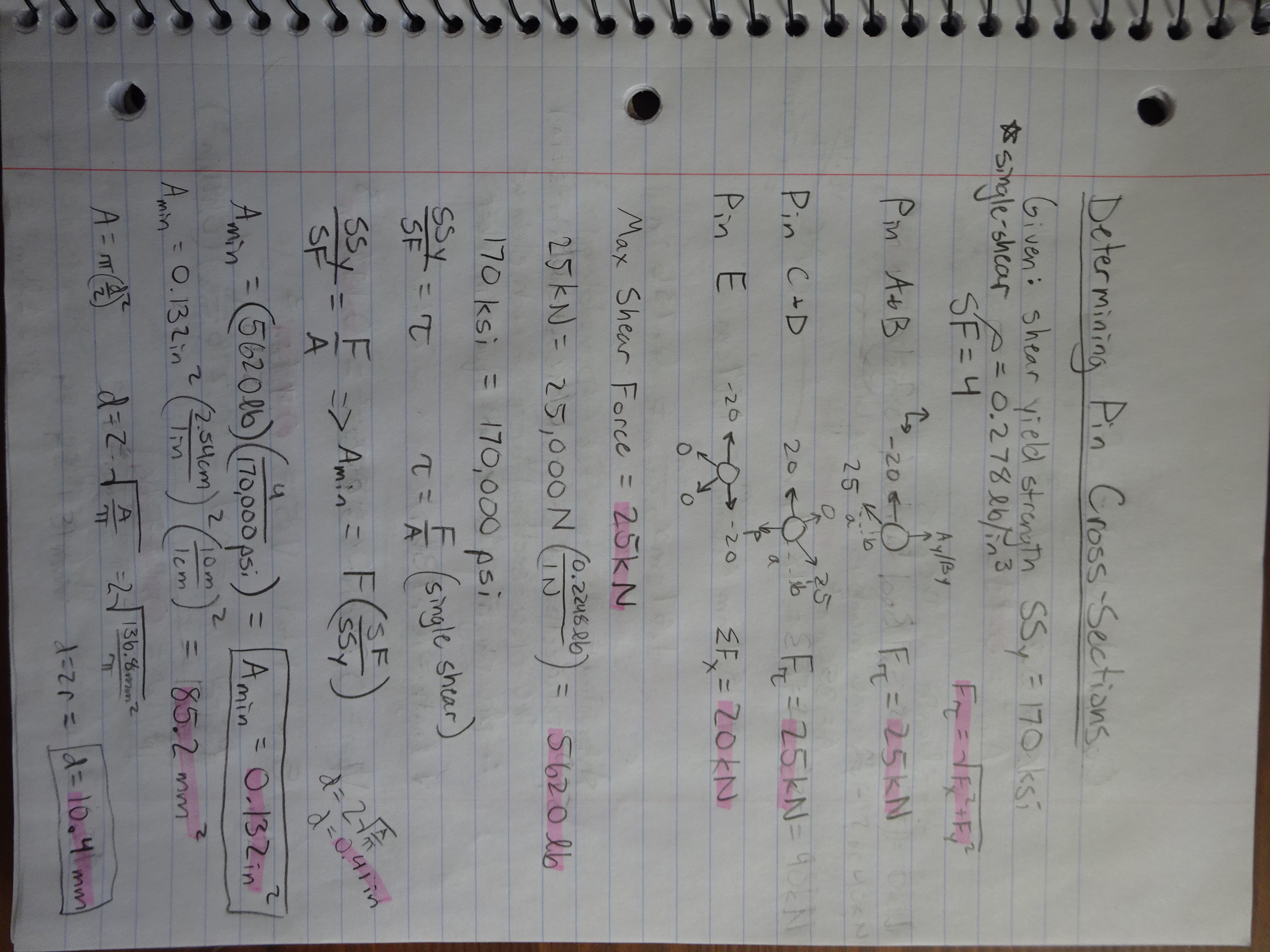
It was also important to design around the pin that would contain the largest shear force in the truss, so I quickly sketched some rough FBD's to calculate the shear at the three unique pins. The max shear force I found was 40kN, and so I began my calculations with that value. Later, I realized that this value was calculated incorrectly and the correct value was lower at 20kN. The assignment specifically stated to solve the pins as single shear, and my work for both the correct and incorrect values can be followed in the image below. I also came back later in the process to calculate the diameter of the pins in both in and mm. The corrected work is shown on the right with the new, correct values highlighted in pink.
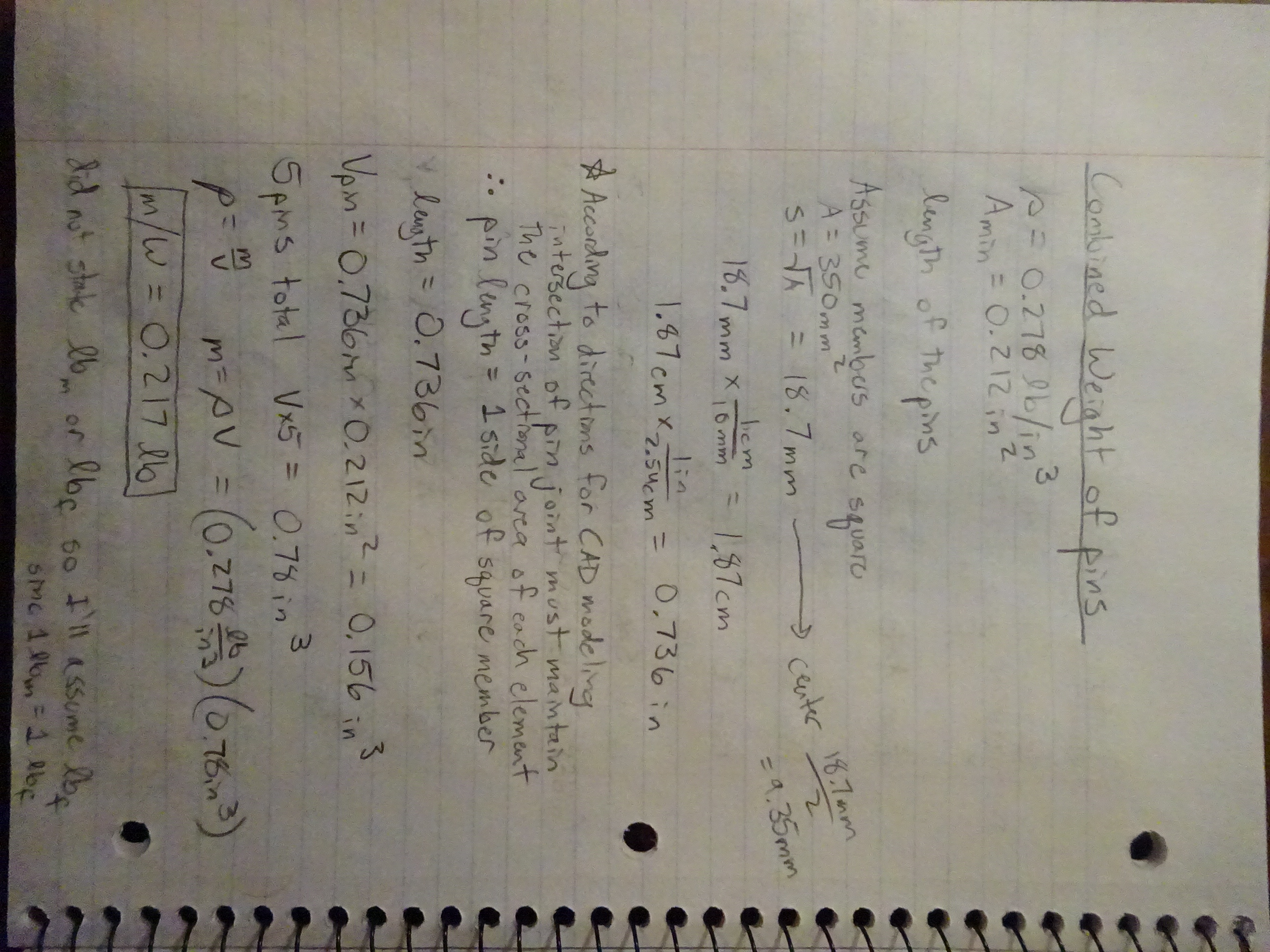
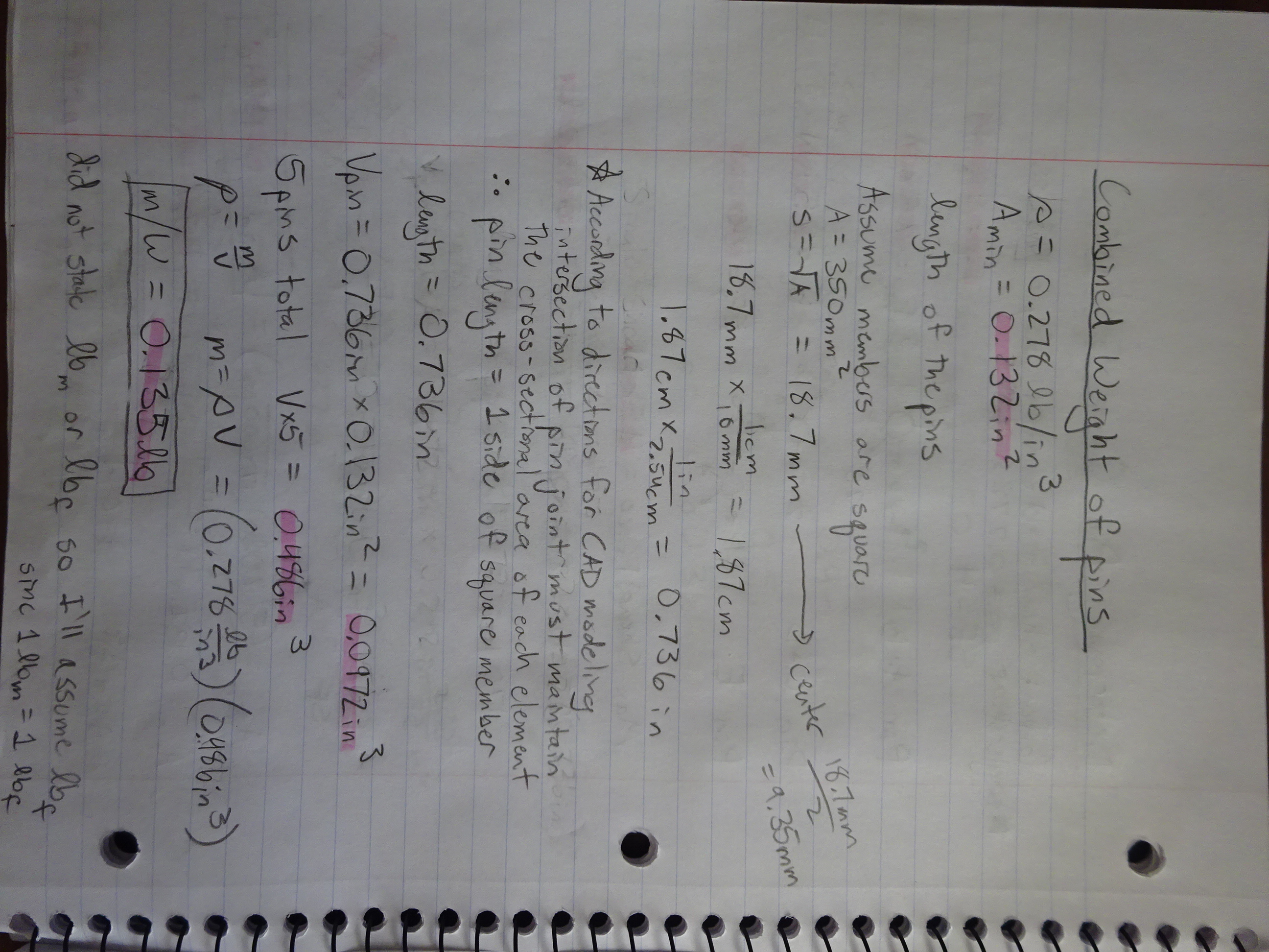
Next, the combined weight of the pins was needed. To do this, the length of the pins had to be determined. Later in the assignment description, it calls for the CAD model to keep the same cross-sectional area at the joints. Using this information, I reasoned that I would model the truss members as square cross-sections and use the length of one side to be the depth of the pins. Using the found length, I could calculate the volume of one pin and multiply by 5 to get the total volume. I could then use the given density to find the weight as seen in the image below. The density did not specify pounds of mass or pounds of force, but since we are on earth the two are equivalent and I can bypass the process of converting mass into force for the weight. This information was also skewed due to the previous miscalculation. The corrected work is on the right with new values highlighted in pink.
CAD Model
To finalize this assignment, the design must be roughly modeled in a 3D CAD Software. Personally, I find that SolidWorks is my preferred software for CAD, and so I utilized it for material values earlier in this assignment as well. I started the modeling process by sketching the length and width for one of the truss members.
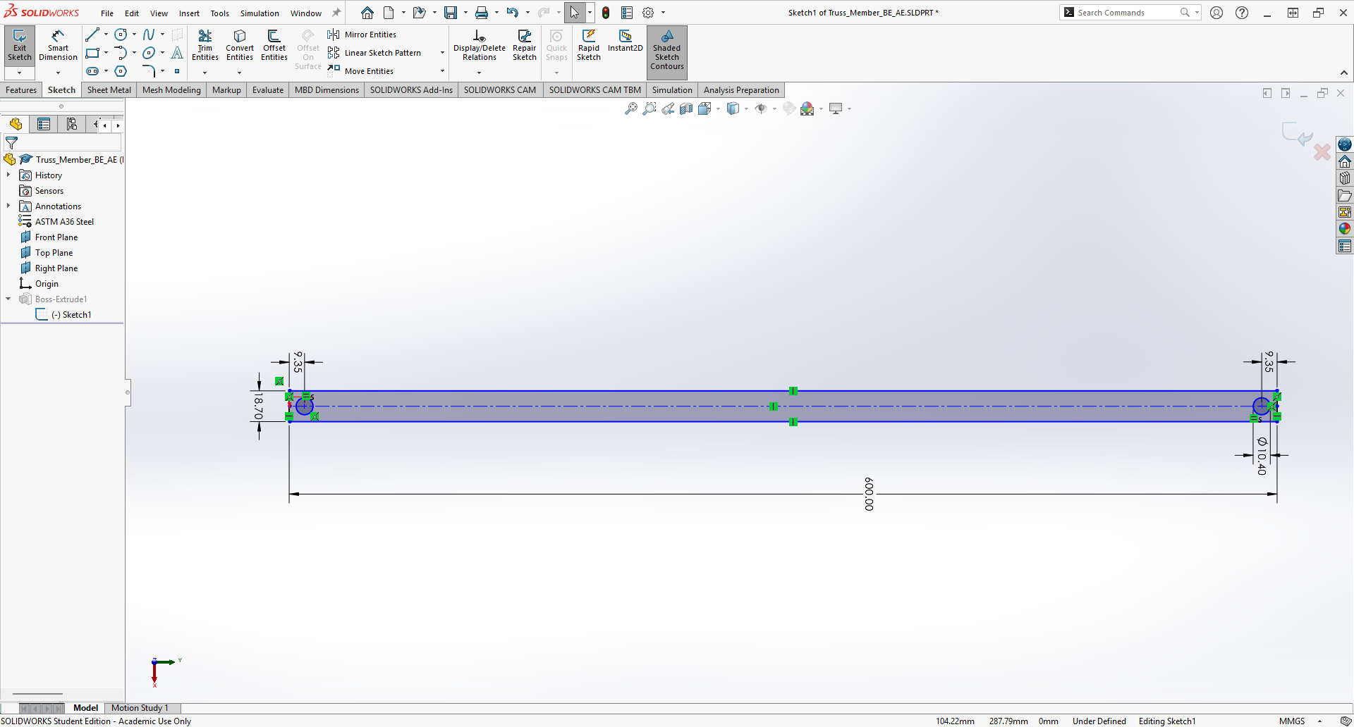

I had a total of four unique, so I went back and edited the length only. I then saved the different lengths separately and labeled the parts with their corresponding member names. After I had the members modeled, I moved on to the pins. I kept the pin model in IPS units since those units were provided in the problem description and I had made my calculations in IPS (Inches, Pounds, Seconds) units. This is different compared to my truss models which were designed in MMGS (Millimeters, Grams, Seconds) units.
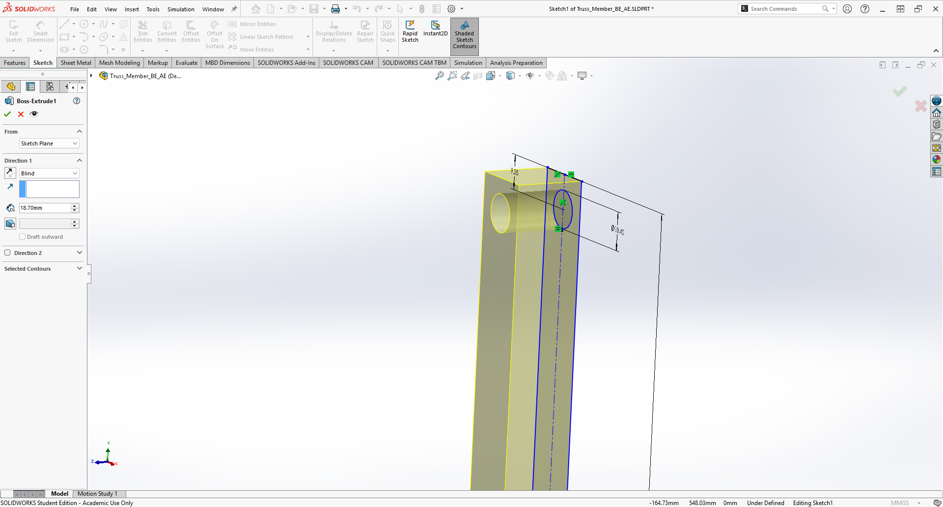
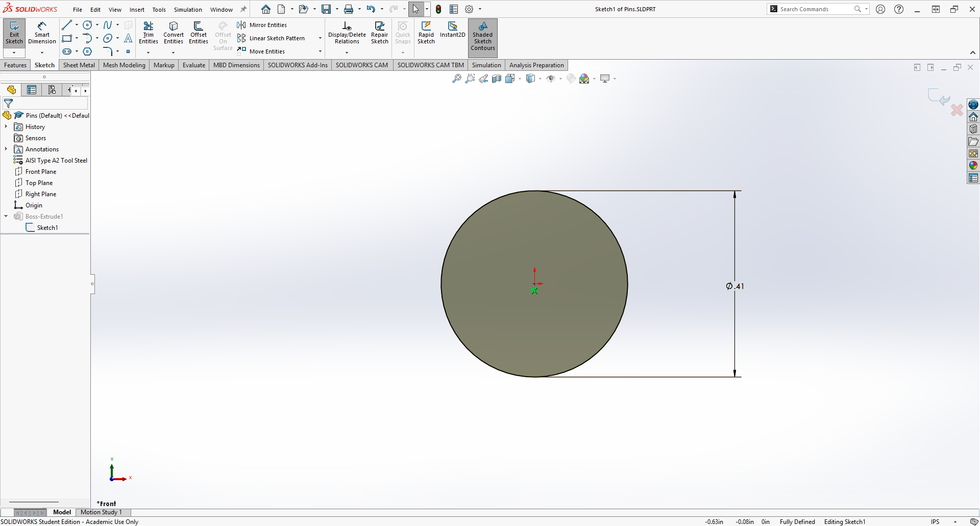
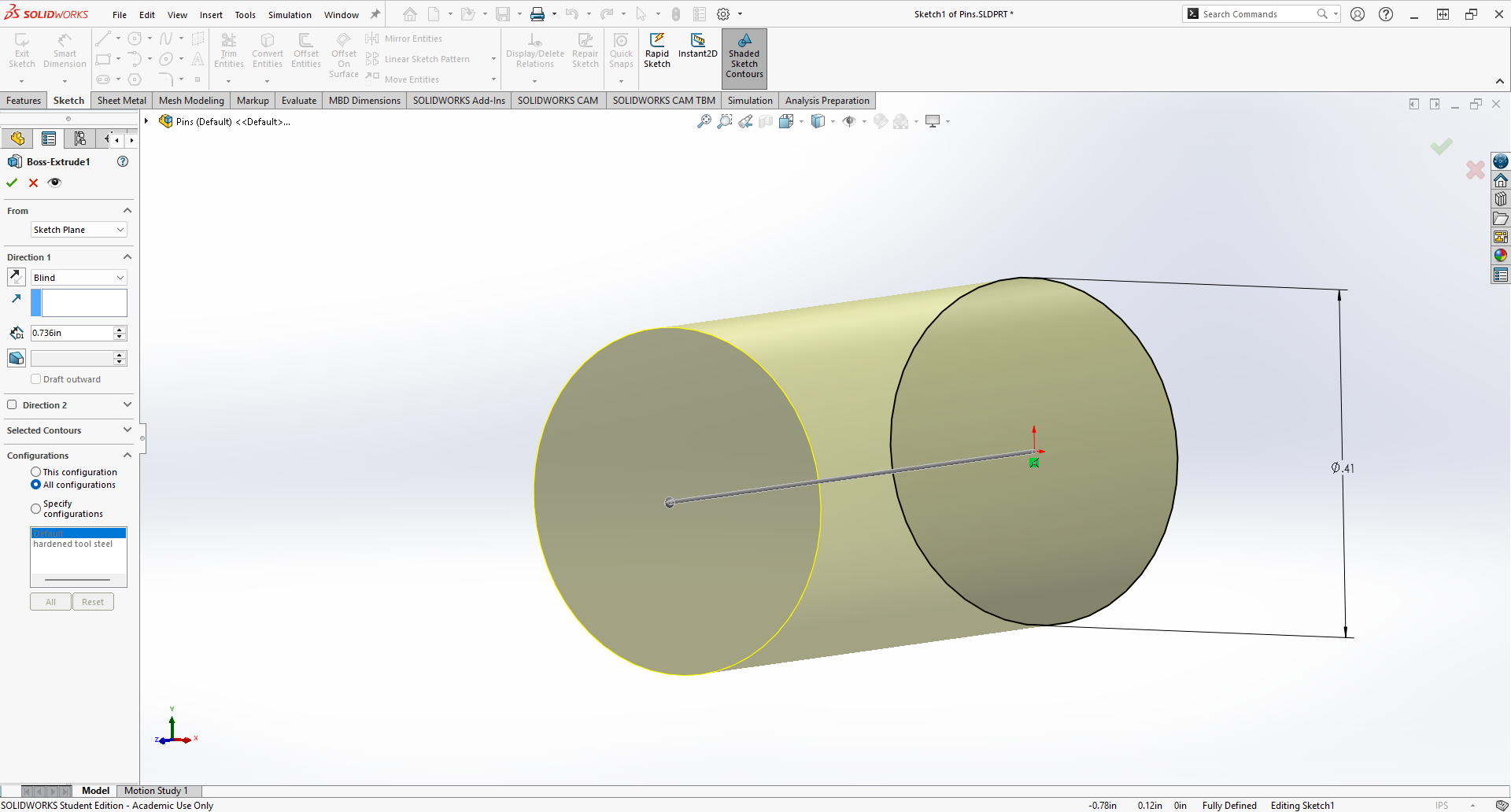
The pin holes on each member had to be converted from inches to millimeters, and at first I made an incorrect conversion which made the holes far too small on the members. Fortunately, when I put together the assembly I quickly caught the error and was able to go back and edit the hole diameter in the members with the accurate conversion values. The images below show the sketch and extrusion of the pin model followed by a closeup of the pin connection at Joint A. Despite the need for unit conversions, I was able to get a tight fit. This is impractical in real life applications, but for the purpose of this model it is okay to have no tolerance between the pins and the truss members.
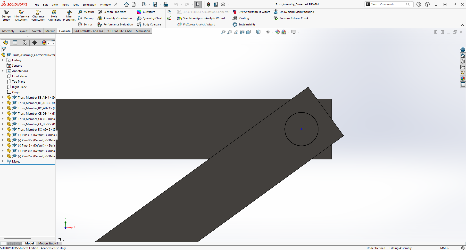
The purpose of this assignment was not model accuracy, and I knew that the lack of tolerance in hole diameter would not affect the objectives of this assignment. I instead finished up the assembly by importing all seven members and five pins before orienting them into their rough locations. Finally, I used the SolidWorks mates to align all elements by their holes' center axis and made sure that all faces were coincident with each other. The first image below is a close-up of Joint E of the truss, which highlights the connections of members with the pin. This is followed by an image of the full truss assembly.
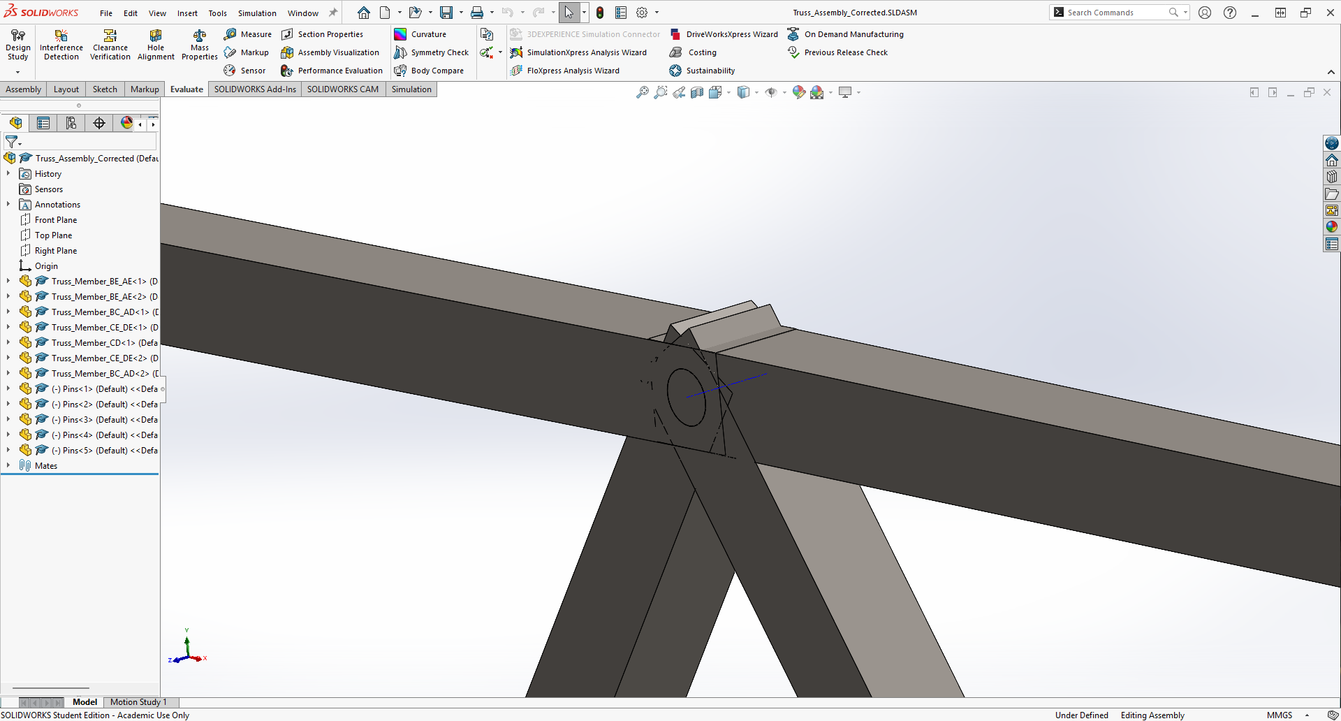
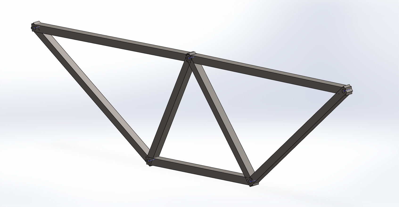
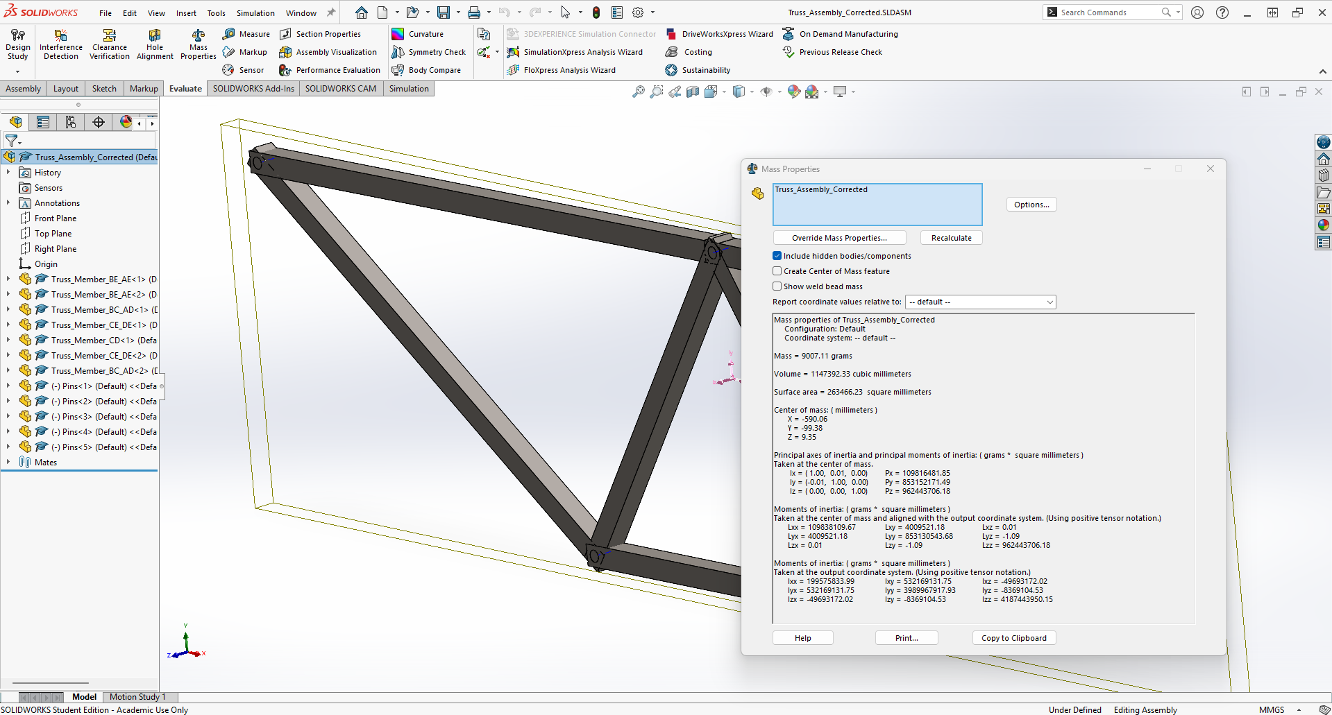
With the model fully assembled, I could move onto the last step of finding the predicted weight in SolidWorks. To do this, I checked the mass properties of the assembly while ensuring that each part still had the proper material in its model-tree. SolidWorks gave me a total mass which I then used to calculate the final weight.
I then made sure to add up both the weight of the truss members and the weight of the pin from my hand calculations, and converted the pins from pounds to Newtons. I was then able to compare the final answers.
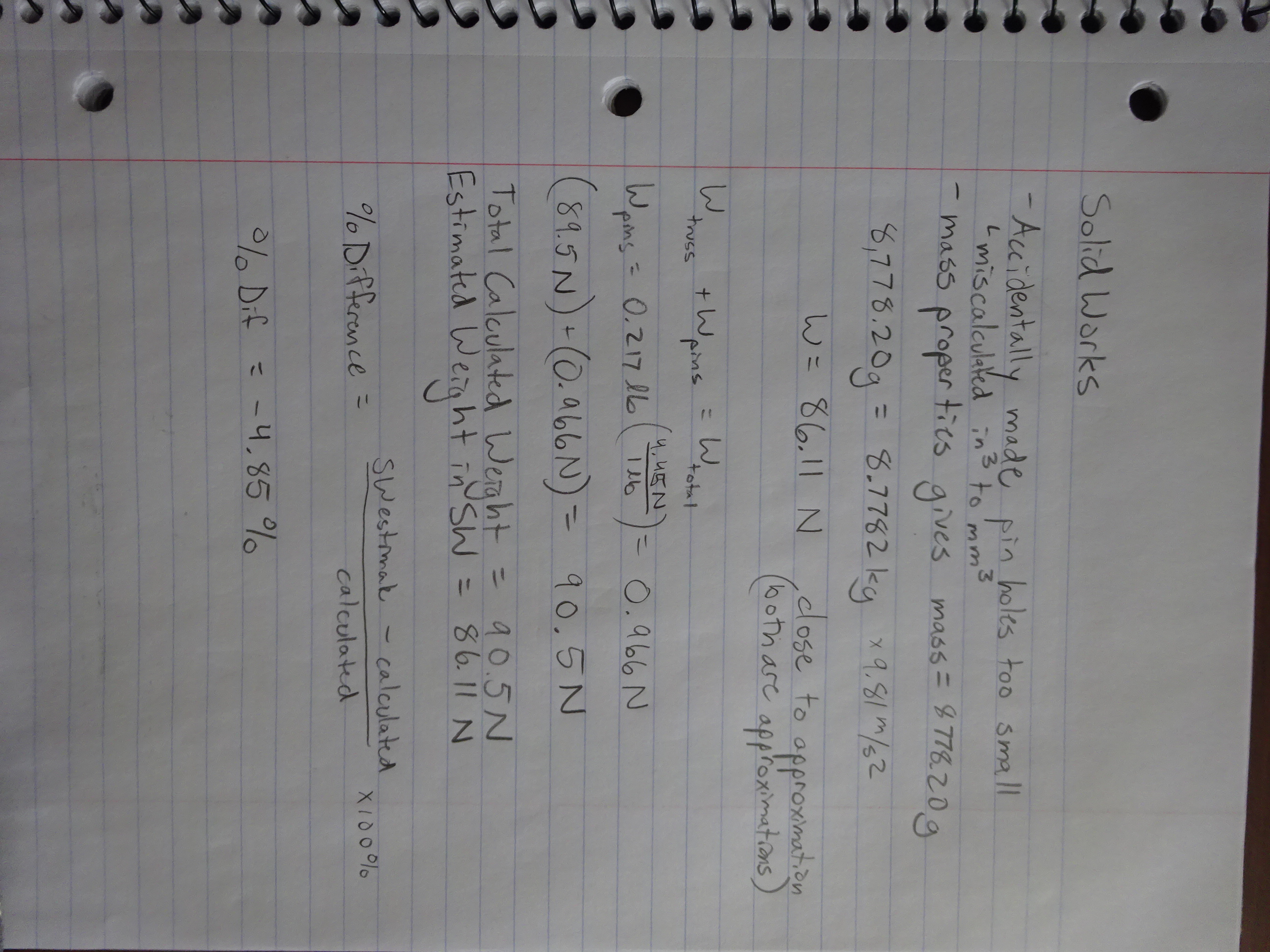
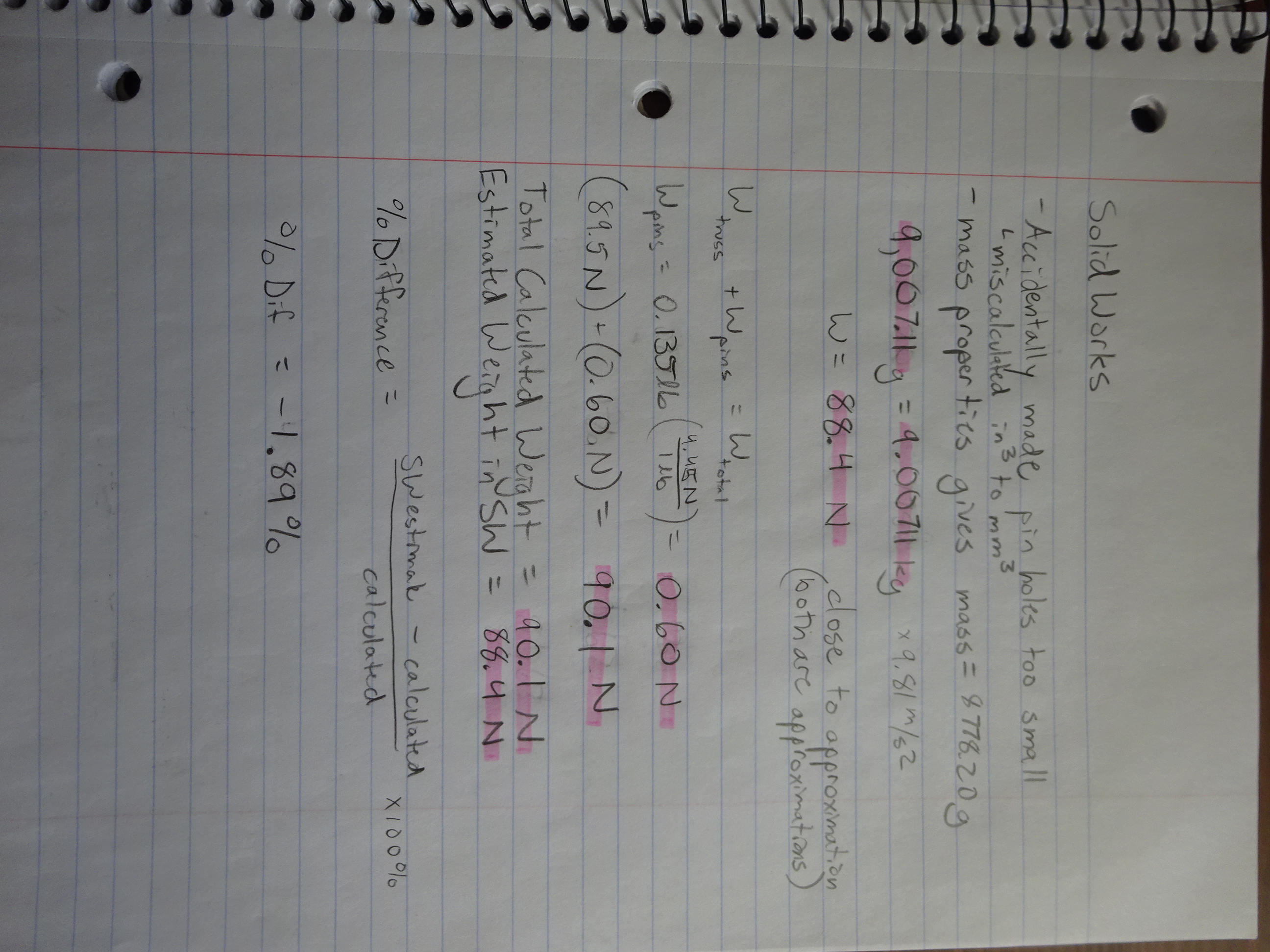
I originally had two incorrect values due to the miscalculation of shear force on the pin as well as an incorrect CAD Model. I was able to go back and correct both values, but this was another important reminder to be more careful during my design process. For the learning experience, I have kept an image of the incorrect weights and comparison. On the right will be the correct values highlighted again in pink.
You can see my work in both images below, and for the correct values, I got a final predicted weight in CAD of 88.4 Newtons while my hand calculatioins got 90.1 Newtons. I calculated the percent difference which was -1.89%. Compared to my previous math wich yielded a nearly 5% difference, I was happy with only a 1% difference. I did still try to think about what could account for the differences and came to this conclusion. My assumption is that the CAD mass was reduced because of the overlap in members since I did not model end joints to each member and instead cut the hole into their length. This slightly reduced their true lengths compared to my calculations, and additionally the overlapping sections' mass could possibly have been left out in the SolidWorks evaluation. I also removed material for the pins to sit into which could reduce the total mass of the truss members as well. I feel that it is satisfactory to have this difference in approximate weights, since my model was not perfectly accurate and both values were still approximations on their own.
I exported the final truss assembly as a .zip file so that it can be easily downloaded and viewed on one's personal CAD software.
Here is the download to the Full Truss Assembly zip file.
For convenience, I also have a pdf copy of all the written calculations. While I do have a copy of the pdf with the incorrect values, I am only uploading the corrected work.
Here is the download to the Written Calculations pdf with the corrected values.
Engineering Lessons Learned
This assignment taught me a lot about design. Specifically, I learned how many options there are to consider and the difficulty of making small errors. I went through only two designs and caught three small errors, but I still spent many, many hours going through each step of the design process that we were given. In the future, I will take this knowledge and experience into consideration so that I can be more direct when coming to a design that I want to pursue. I also know just how infuriating it can be to spend hours getting the wrong answer because of a simple miscalculation or forgotten variable earlier in the process. This compiling of error is dangerous, and it required me to numerically rework most of this project. This did have the addition of reminding me how helpful it is to have symbolic interpretations of answers, so that I can change values on the fly and adjust for the corrections. In future projects, I will surely take more care in each step so that I do not fall into a cycle of getting stuck on an error and repeating a process more than I need to.
In addition to design challenges and errors, I learned a lot about materials like A36 and A500 steels. I needed to find trustworthy information on substitute material and locate a correct yield strength for my calculations. This was also one of my first times going through the necessary calculations to define a truss design, and so it forced me to better understand the principals I've learned in Statics and now Solid Mechanics. The challenge of designing makes me excited for the future, as I am now learning and practically applying the content from many different engineering courses that I have taken at UNC-Charlotte.