
Pulley System Design
Assignment Description
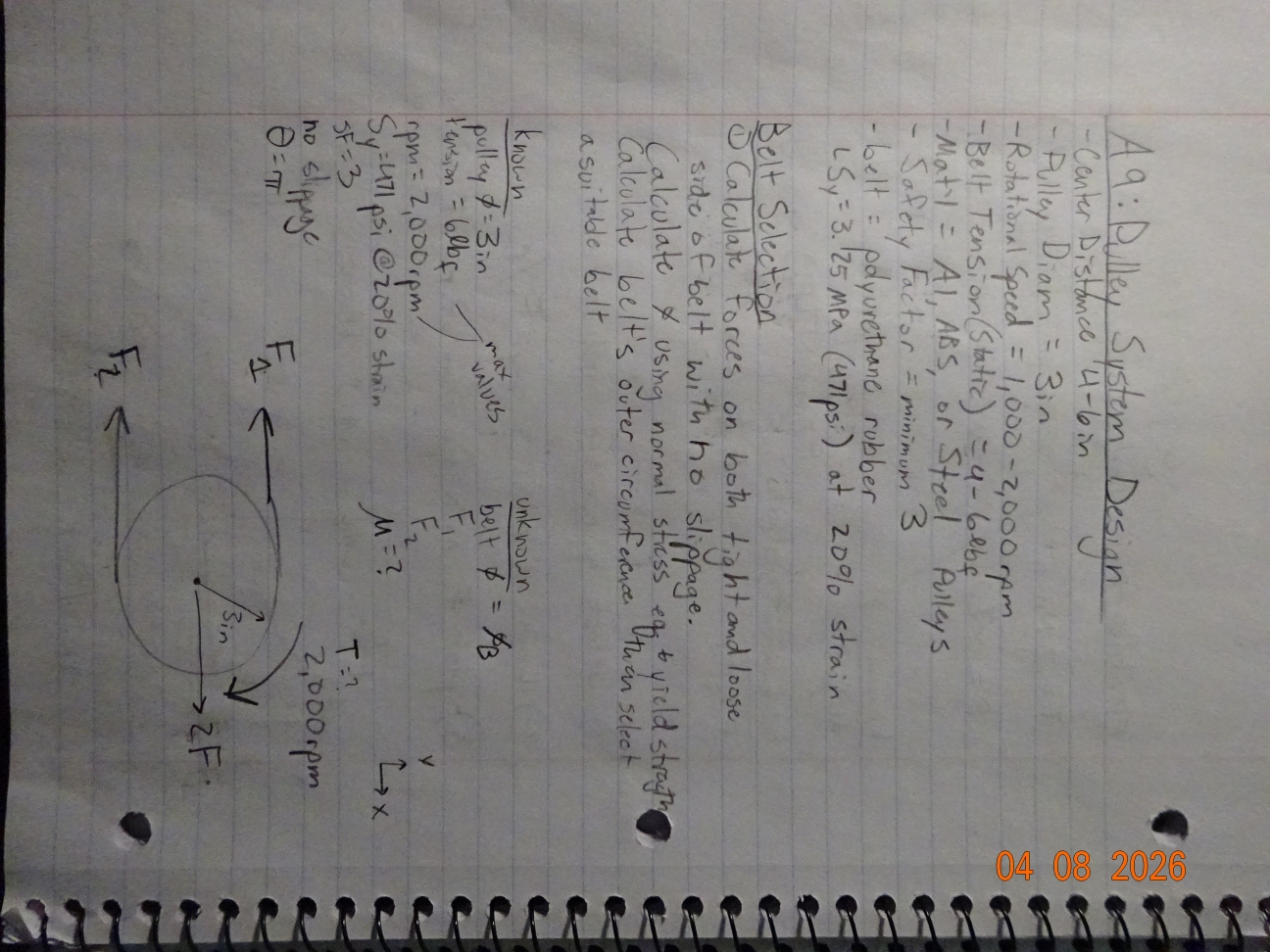
Design a pulley system to transfer power between two parallel axes separated by a center distance of 4–6 inches. The system must meet the following requirements:
- Pulley Diameter: Both pulleys shall have a diameter of 3 inches.
- Rotational Speed: Select an operating speed between 1000–2000 rpm.
- Belt Tension (Static): Select a belt tension between 4–6 lbf under stationary conditions.
- Material: Pulleys may be made from aluminum, ABS, or steel, and may include a groove and shaft diameter of your choosing (within reasonable manufacturing limits).
- Safety Factor: The design must satisfy a minimum safety factor of 3.
Assume the belt is made from polyurethane rubber, with a yield strength of 3.25 MPa (471 psi) at 20% strain, based on: Wanga, Chena, Wua, Zhangb, Suna, “Strain-induced Structural and Dynamic Changes in Segmented Polyurethane Elastomers.”

Figure #1 shows the force and geometric constraints of the design problem.
Note: All Description info comes directly from the assignment given by Dr. Fagan
Belt Selection
As usual, I find it important to hand write down all necessary information given in the assignment description. Below this, I start the process of selecting the belt for the pulley system. The first page shows the known and unknown variables as well as the free body diagram that I referred to as I modeled my equations.
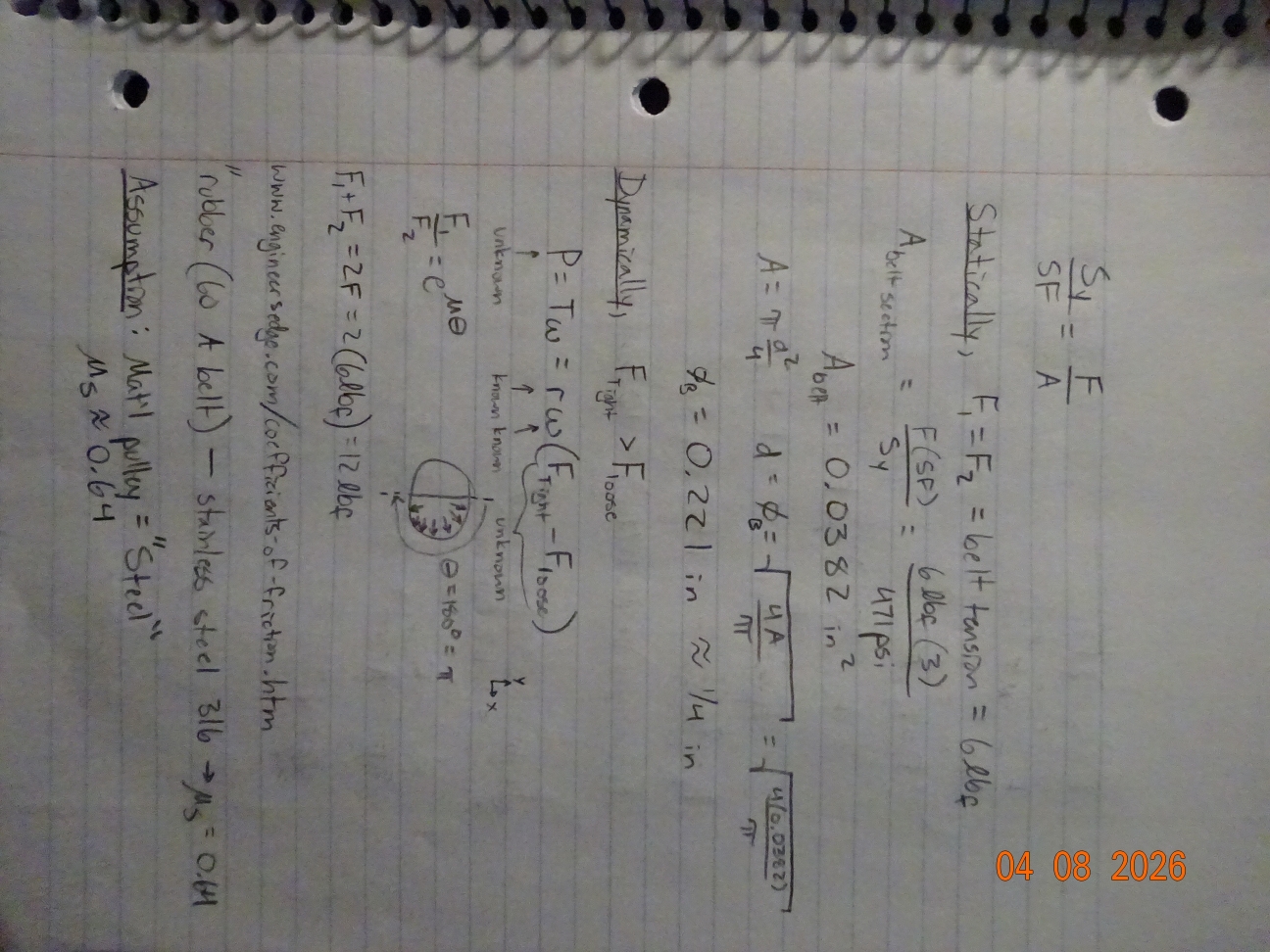
To solve for the tight and loose forces of the belt on the pulley, I first do a static analysis of the forces. This gives the resultant force at the center of the pulley as 2 x the static belt tension. I utilized the max of the static belt tension range which is 6 lbf. I was also able to determine a belt diameter from the static analysis which gave a value of 0.221 inches or roughly 1/4". I continued by evaluating a dynamic analysis of the pulley system. I started by showing that F_1 > F_2 as the tight side of the best is greater than the loose side of the belt. I then utilized the belt slippage equation in conjunction with the dynamic equilibrium equation of F_1 + F_2 = 2 x static belt tension. However, before combining these equations, I needed to find the coefficient of friction for the model. I utilized the site, www.engineersedge.com, and found that the static coefficient of friction for rubber (60 A belt) on stainless steel 416 is roughly 0.64. With this information, I made the assumptions that I would utilize steel as the material for the pulleys and treat the coefficient of friction as equal to the data I found for a rubber belt on stainless steel. This may not be exact, so I am acknowledging it as an assumption that could be corrected with additional information/data.
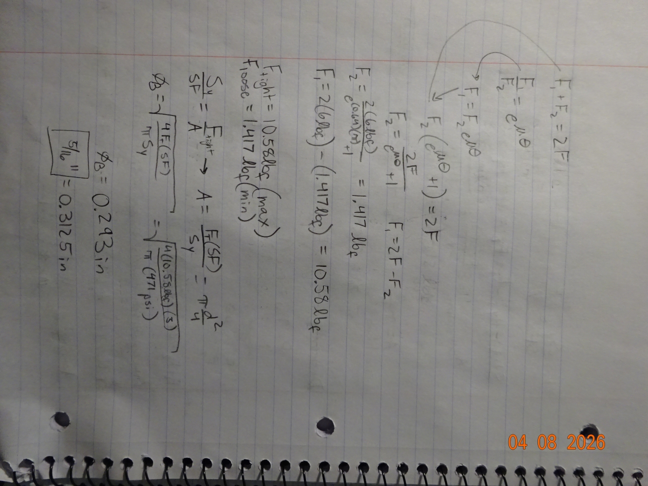
I continued with the dynamic analysis utilizing my assumptions to complete the calculation for F_1 and F_2, the tight and loose forces respectively. I found the maximum tight force on the belt to be 10.58 lbf and the minimum loose force on the belt to be 1.417 lbf. I utilized the max force in the normal stress equation to solve for the diameter of the belt. The dynamic analysis resulted in a diameter of 0.293 inches. For simplicity in finding a belt later, I rounded up to 5/16".
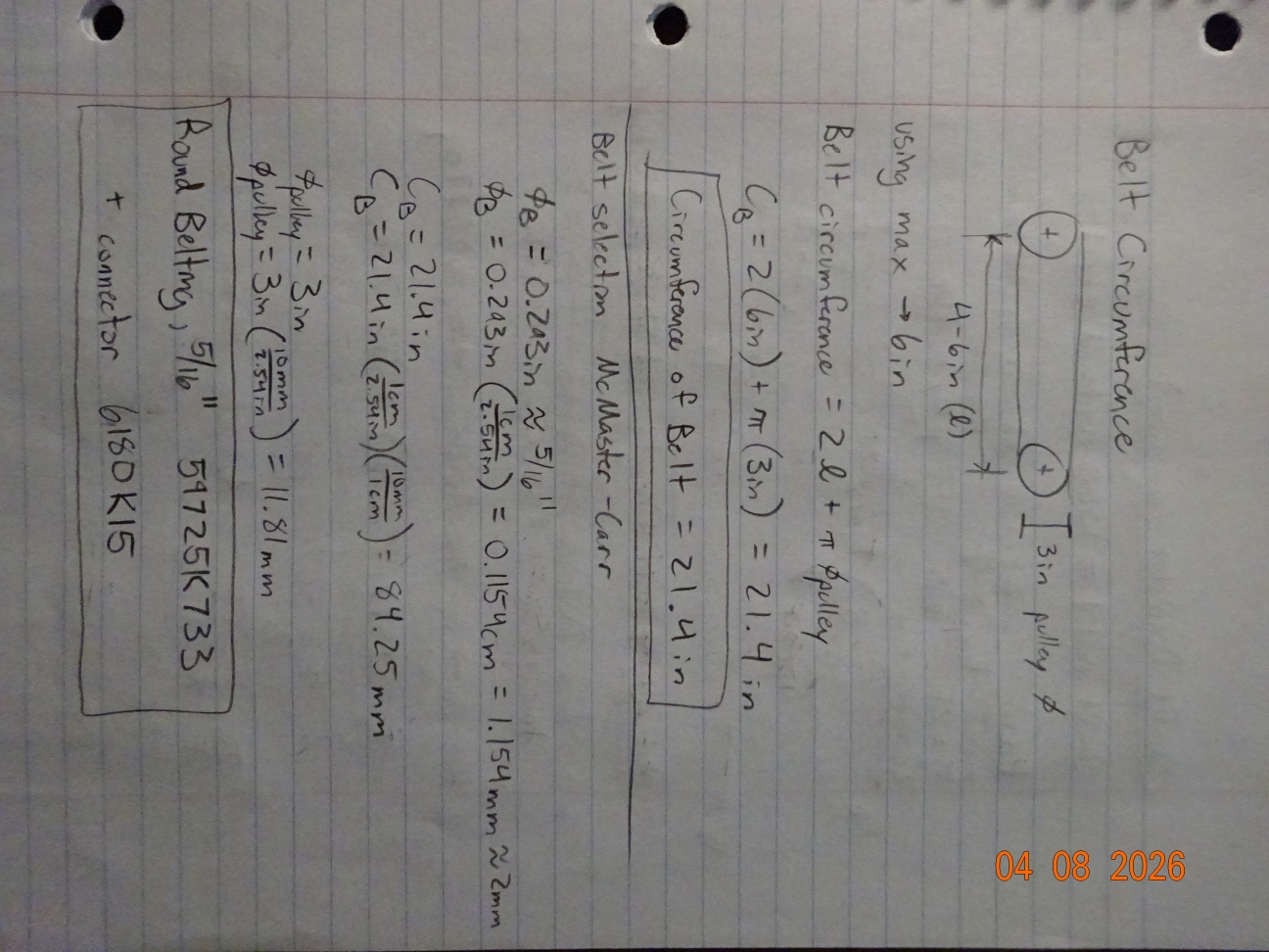
After finding the diameter, the circumference of the belt was needed. I drew another small free body diagram and found that the circumference would need to be equal to 2 x the center distance between the pulleys + the circumference of one pulley. I utilized the max center distance of 6 inches and found the belt circumference to be 21.4 inches. I was then able to look for a belt on McMaster-Carr. Some of the belts were in metric units, so I converted my diameter and circumference to mm. My final selection was Round Belting, 5/16" with a connector. The part numbers are 59725K733 and 6180K15 respectively.
Shaft Diameter
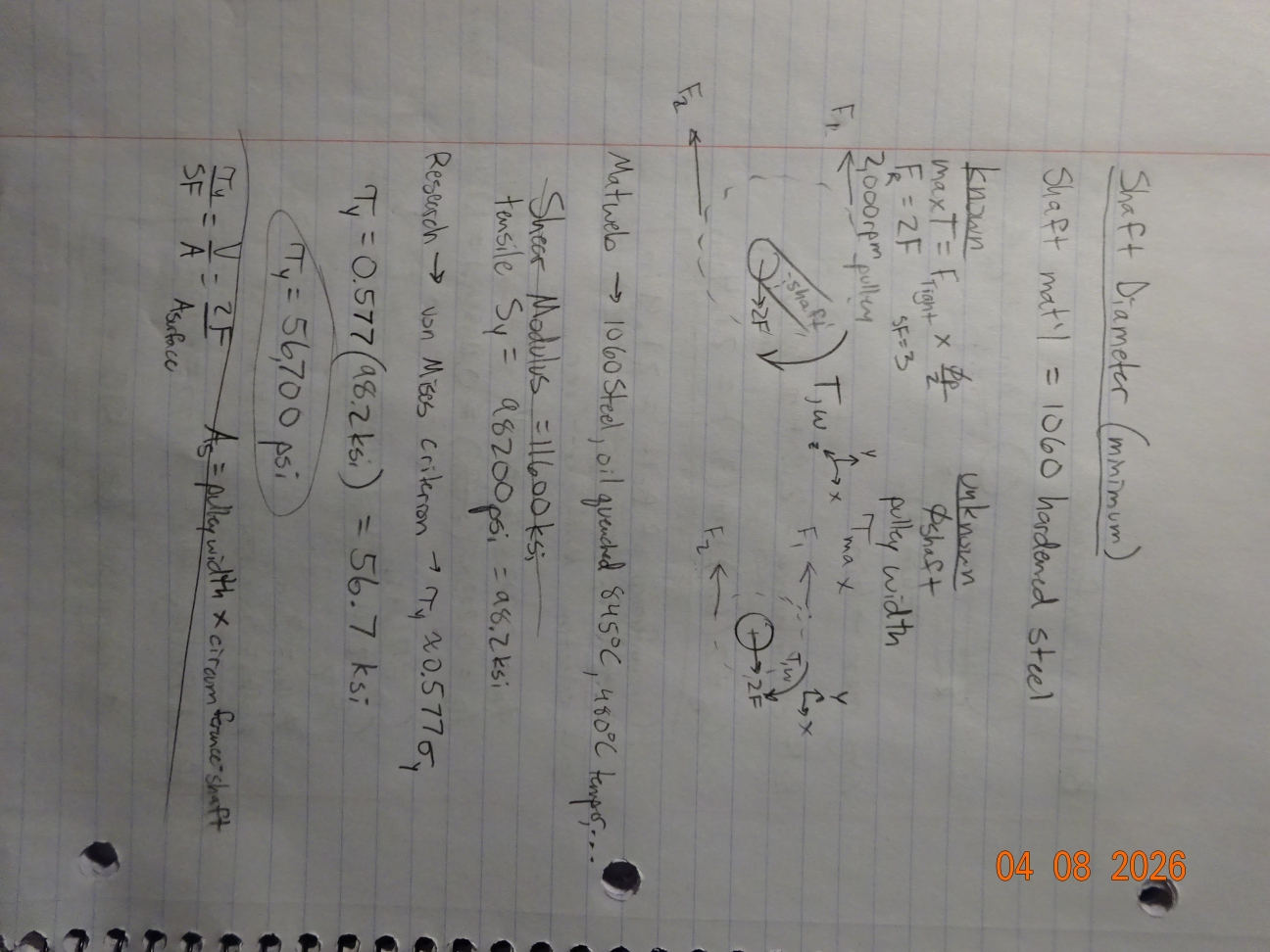
The shaft is supposed to be made of 1060 hardened steel. I started by writing down the known and unknown variables along with some small free body diagrams that I referred to as I modeled my equations. One of the missing values was the shear yield strength. To find this value, I first went to matweb.com and found some values for AISI 1060 steel, 480 °C temper. The shear stress was not given, so I wrote down the tensile yield strength. I then did some research and found that it is possible to estimate the shear yield strength from the tensile yield strength using the von Mises criterion. This says that the shear yield is approximately 0.577 x the tensile yield. From this, I was able to determine that the approximate shear yield strength is 56,700 psi for 1060 hardened steel.
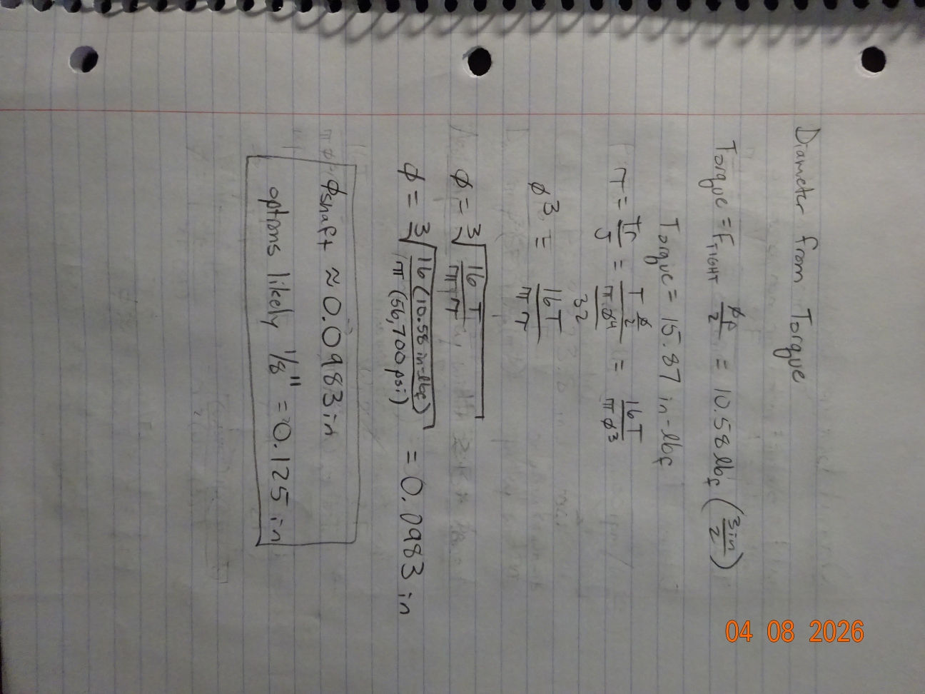
Next, I determined the minimum shaft diameter by using the equation shear stress = (Torque x radius)/(J). I then solved algebraically before coming to the final diameter. While writing up the portfolio documentation, I realized that I had forgotten to include the safety factor in this calculation. Since it was modeled algebraically first, I was able to come back and add the safety factor in the numerator and find a corrected diameter of ~0.14 inches. I had originally rounded up to 1/8" but now need to round to 3/16" for the diameter of the shaft. The shaft diameter is used later in the bearing calculation, so I will state the updated values there as well.
Journal Bearing Design
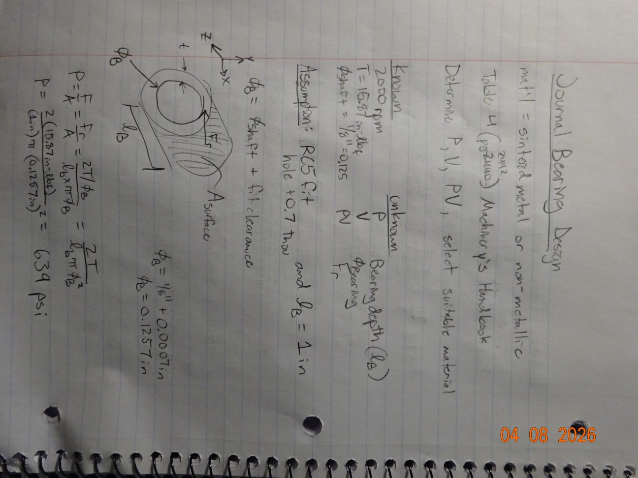
The journal bearing was to be made of sintered metal or non-metallic material. I started by writing down the known and unknown variables and drawing a free body diagram. I made two assumptions in this design for the bearing length and fit for the bearing and the shaft. I assumed a bearing length of 1 in and a fit of RC5. Following the corrections made in the previous section, an updated bearing diameter would be 3/16" +0.7 thousands of an inch. This gets a bearing diameter of 0.1882 inches. This value then gives a new pressure of 285 psi.
The new calculated surface speed is 98.5 ft/min. The new PV rating is 28,108 psi-ft/min. This is a pretty substantial reduction in journal bearing requirements from my handwritten work, but it also means that my original material selection will be more than sufficient for the application of this assignment with the corrected journal bearing values.
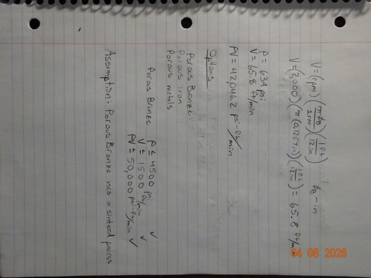
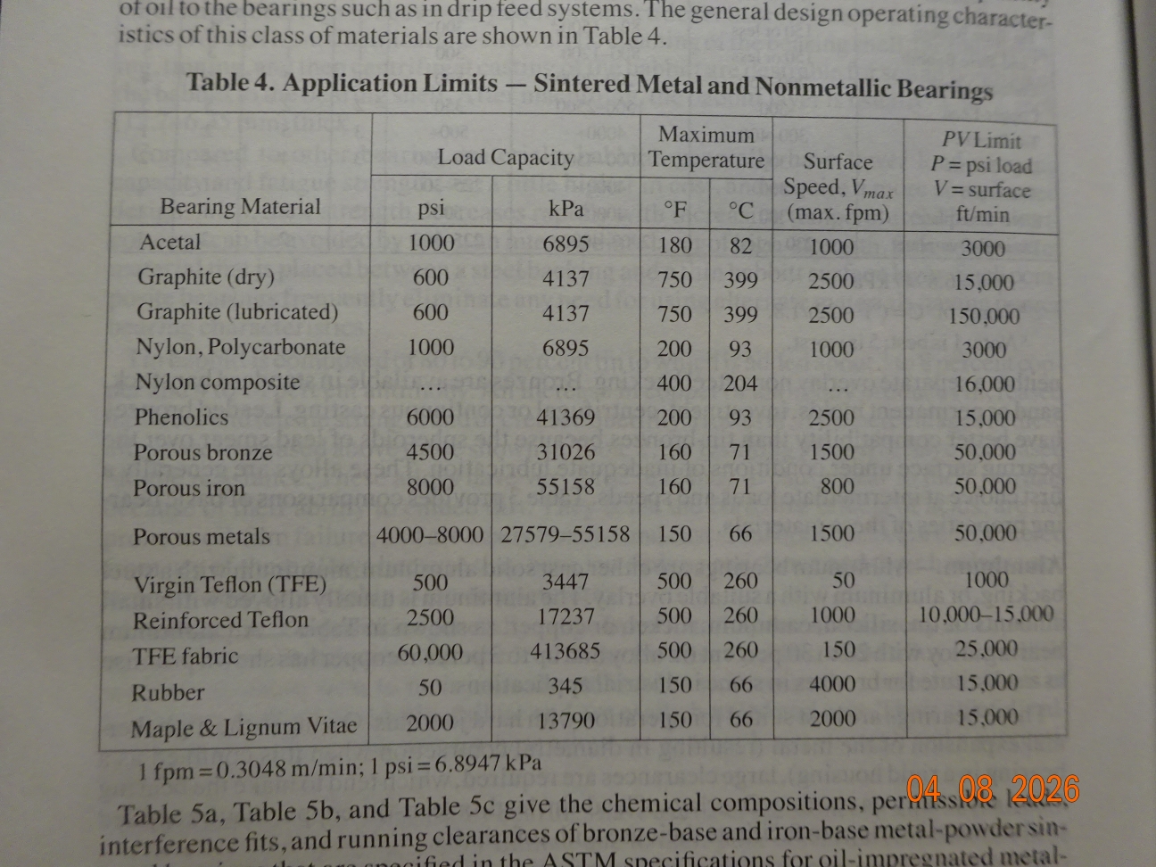
My original selection for bearing material was the porous bronze which I assumed would be made from a sintered process. By looking back at Table 4 in the image below, I can determine that lubricated graphite would also have been a viable material. Ultimately, any porous metal should be sufficient as seen in the chart.
Frame Design
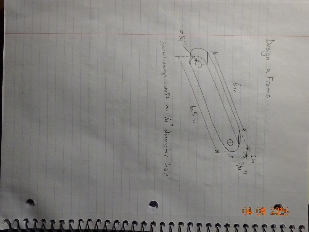
The final task for this assignment was a rough frame design using engineering analysis. I dimensioned my sketch using information from the previous design calculations. I had already oversized the hole for the journal bearings to include a nominal thickness of the bearing, and so the 1/4" holes in the frame should still be large enough to fit a 1/4" journal bearing that would fit a 3/16" shaft. I do acknowledge that further engineering analysis could be done on the frame to ensure its performance in the pulley system. Overall, the dimensions should have sufficient padding that with a well selected material the frame would be fitting for the application of the assignment.
PDF download: here
Lessons Learned
This assignment taught me the importance of being able to research and look up material properties to make design decisions. I also was reminded why solving algebraically for solutions can be helpful when making alterations or corrections to the design. I gained more practice and better understanding of how to make selections from databases like McMaster-Carr. This was also my first application of utilizing dynamic analysis on a system to solve for forces.
Overall, this assignment took roughly 5 hours to complete.